¶ Part replacement
¶ Nozzle Replacement
When the nozzle is worn out or clogged beyond repair, you can replace the nozzle with a new one.
Replacement procedure:
① Before replacing the nozzle, please reduce the nozzle temperature to room temperature to prevent burning when replacing the nozzle.
② Move the Z-axis up about 150mm or so to make sure there is room for a change.
③ Remove the silicone sleeve from the hot end.
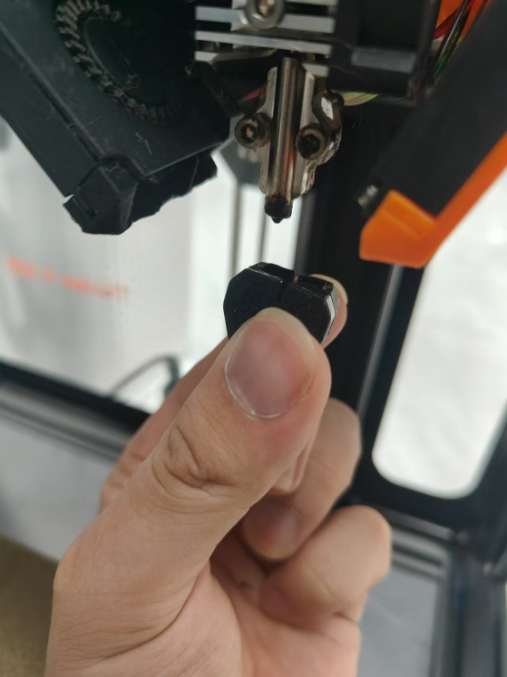
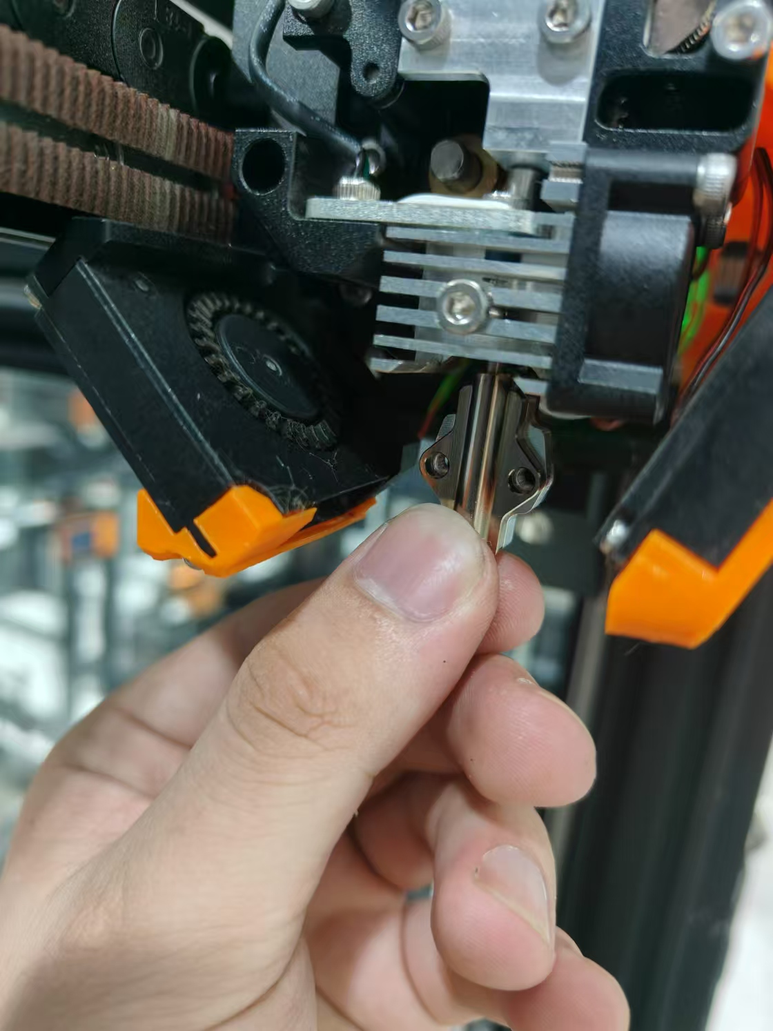
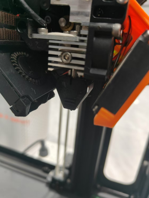
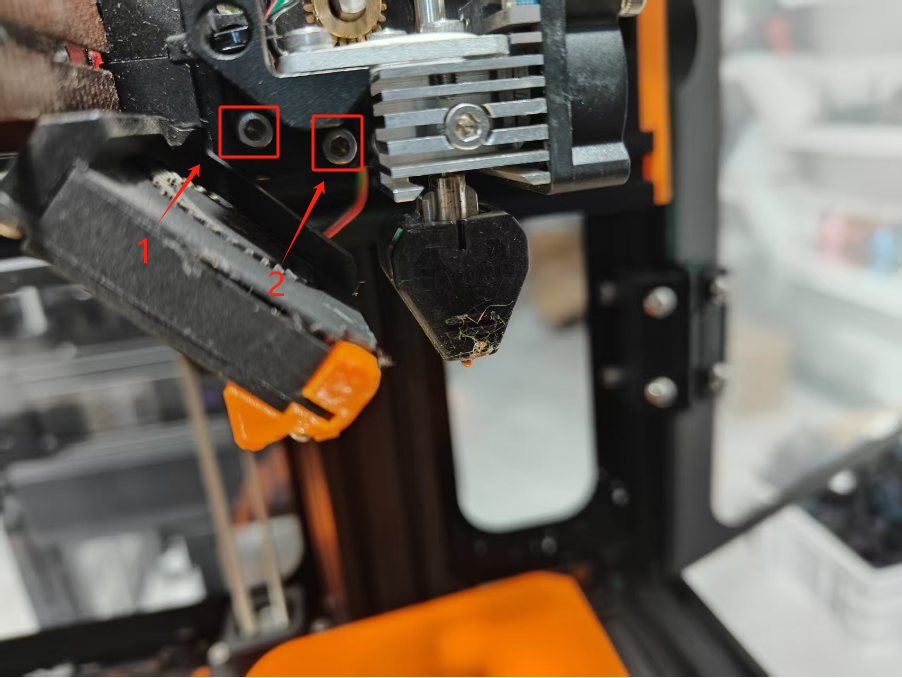
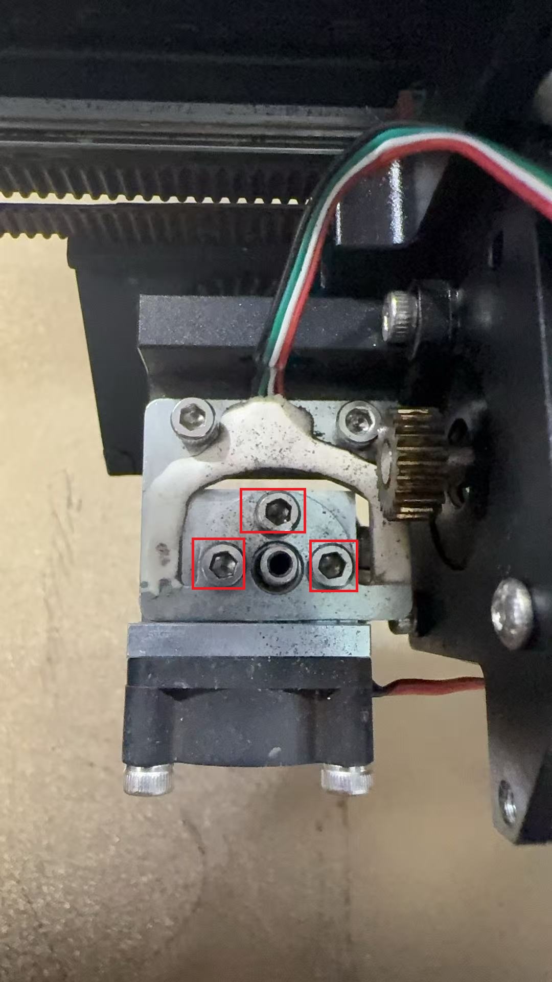
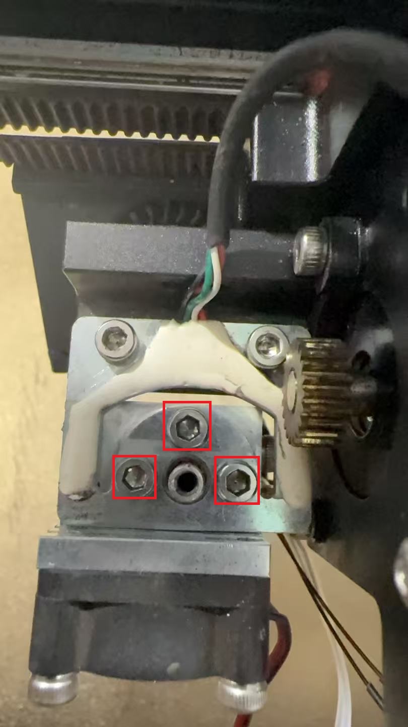
④Use a 2.5mm Allen wrench to remove 2 screws and loosen 1 screw on the heat sink, remove the old nozzle.
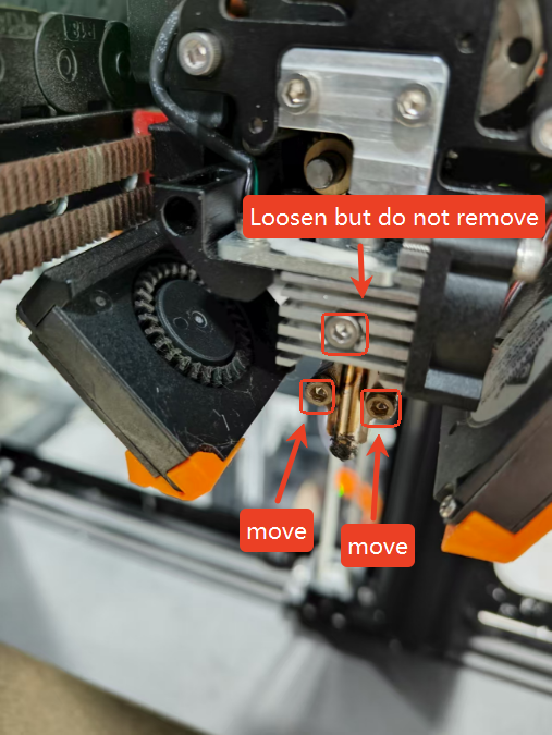
⑤Take the new nozzle, put the smooth end against the hot end, use a 2.5mm allen wrench to reinstall the 2 screws back in, and tighten the screws on the heat sink.
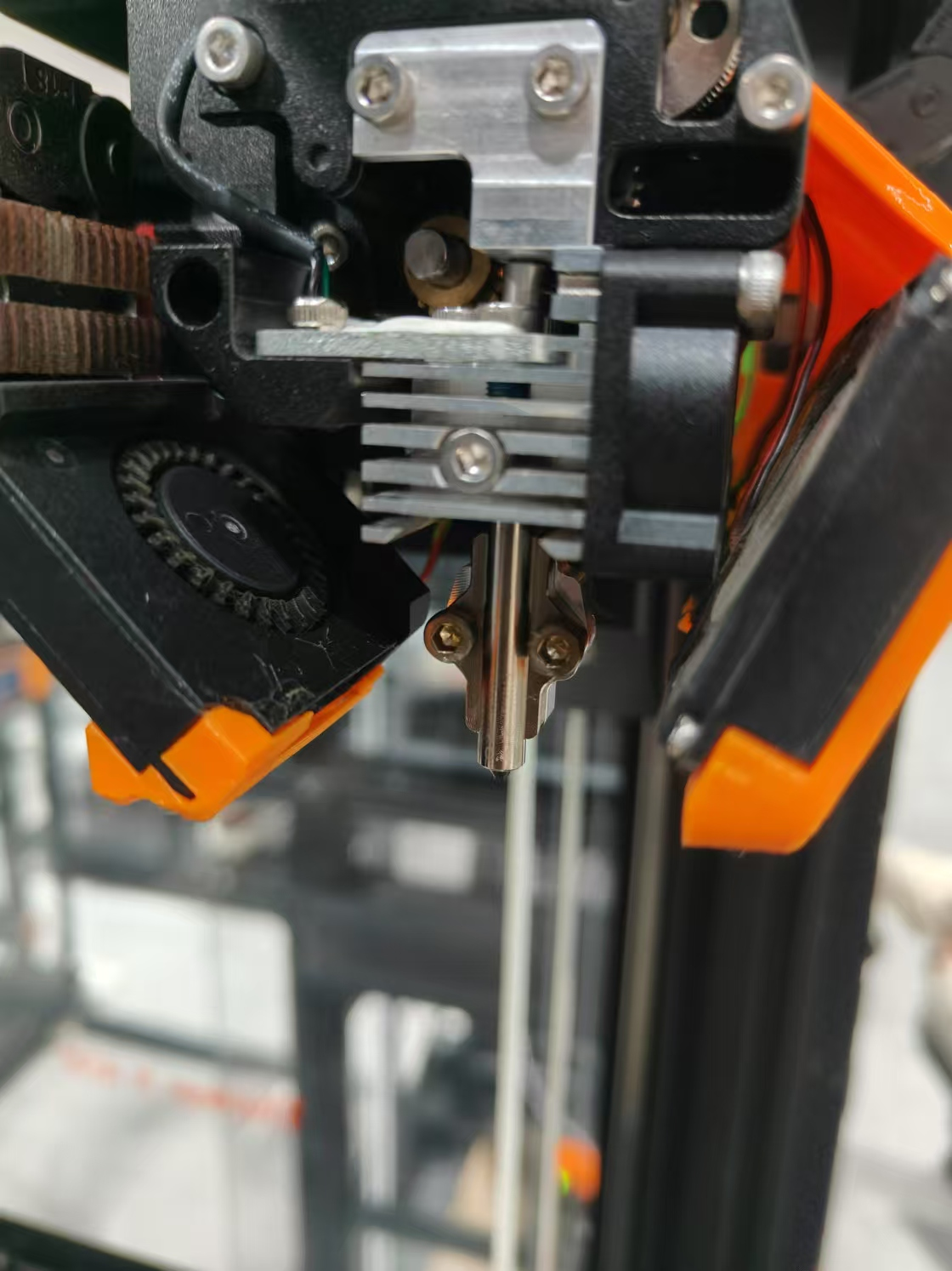
⑥ Put back the silicone sleeve.
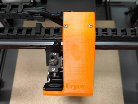
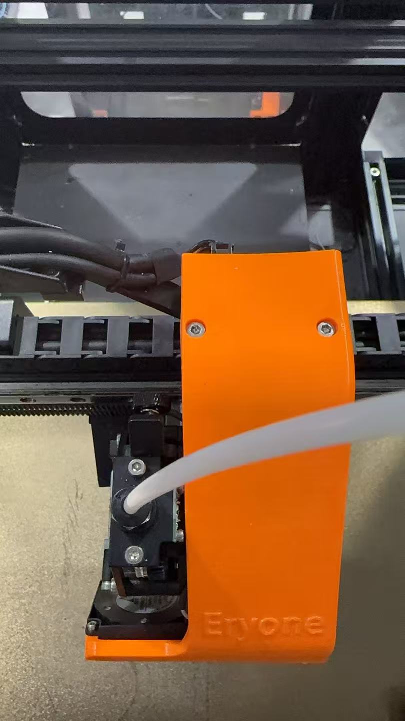
¶ PTFE Tube Replacement
Replacement steps:
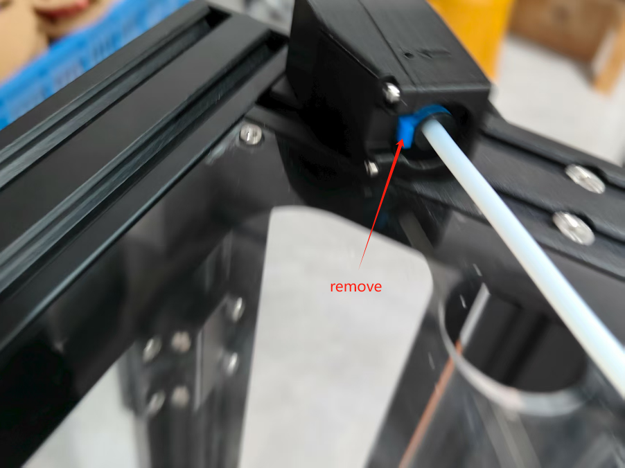
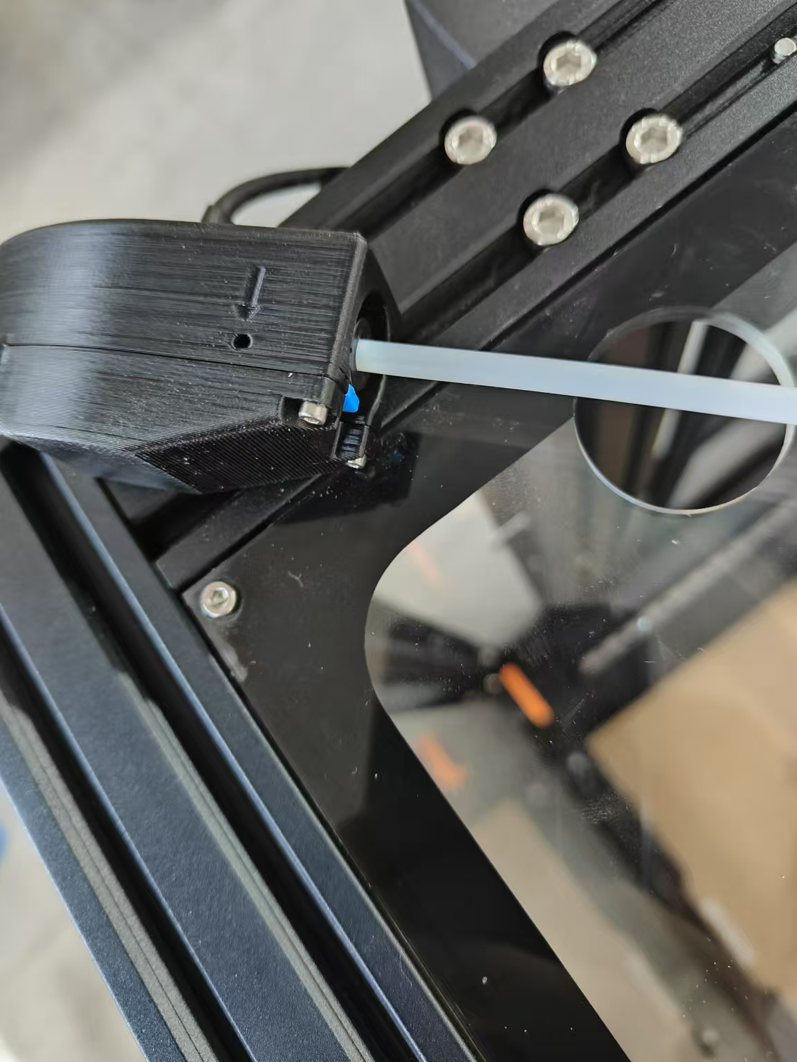
Take out the feed tube retainer.
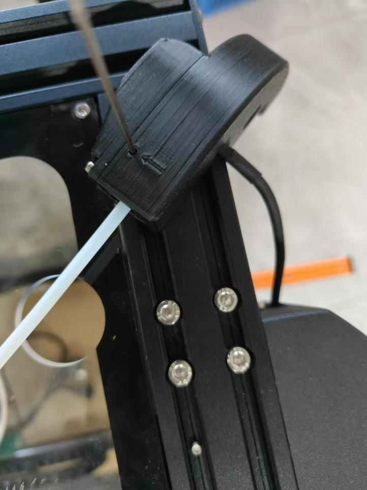
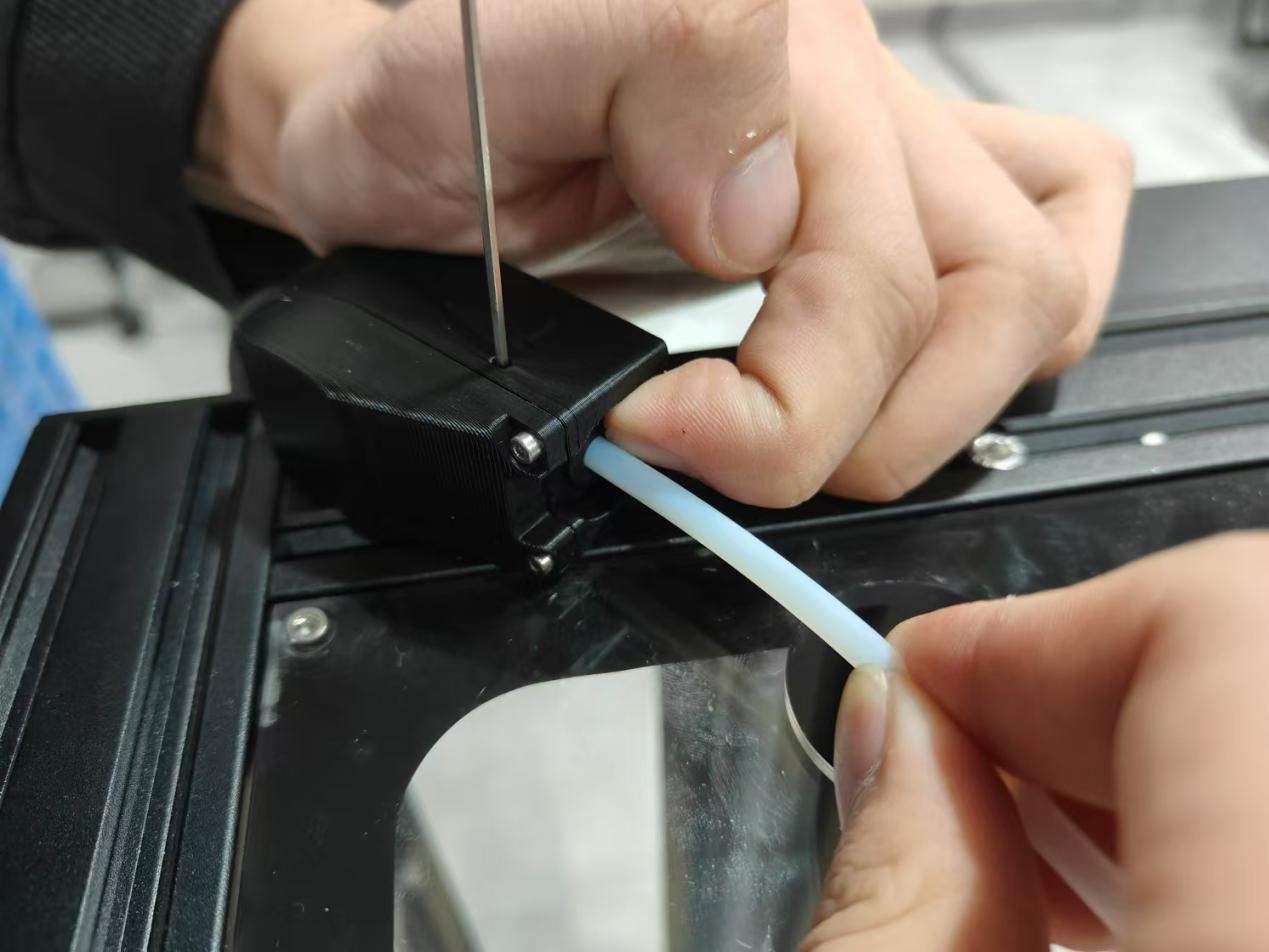
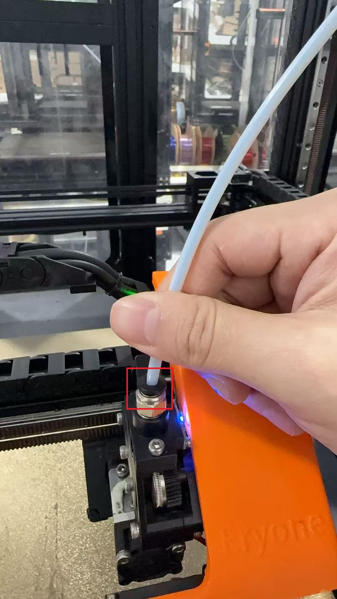
Use a 1.5mm Allen key to insert into the upper hole.
③Hold the plug of the pneumatic connection with one hand and pull out the PTFE tube with the other hand.
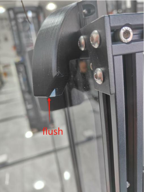
④Insert a new PTFE tube until it is flush with the Teflon catheter seat port.
⑤To install the return tube retainer, pull out the 1.5mm Allen wrench.
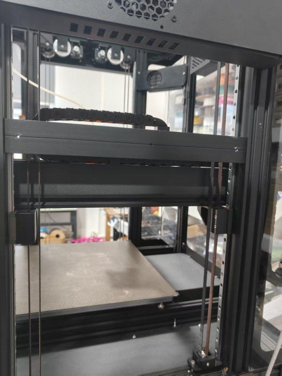
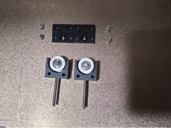
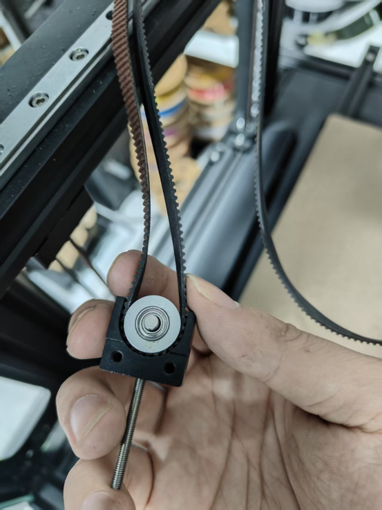
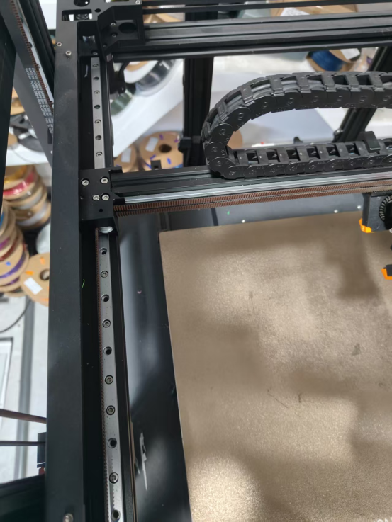
¶ Z-Axis Belt Replacement
Replacement steps:
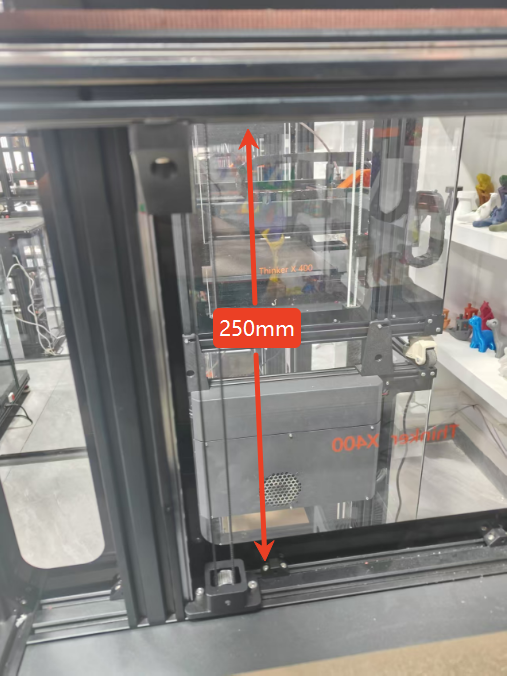
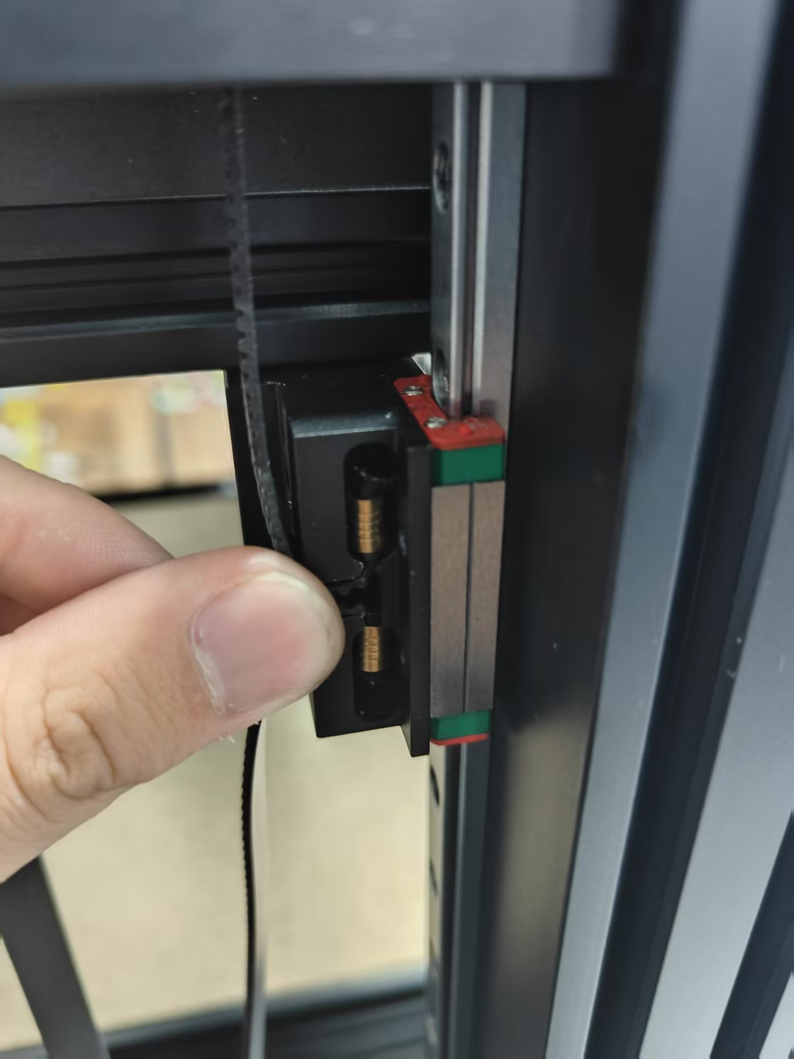
1.Raise the Z-axis 250mm upwards (make sure there is enough space to remove the screws).
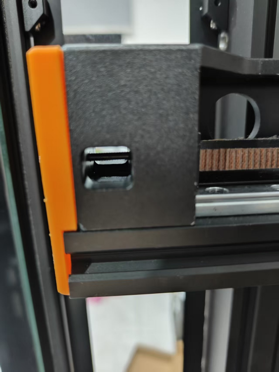
2.Removal of acrylic panels.
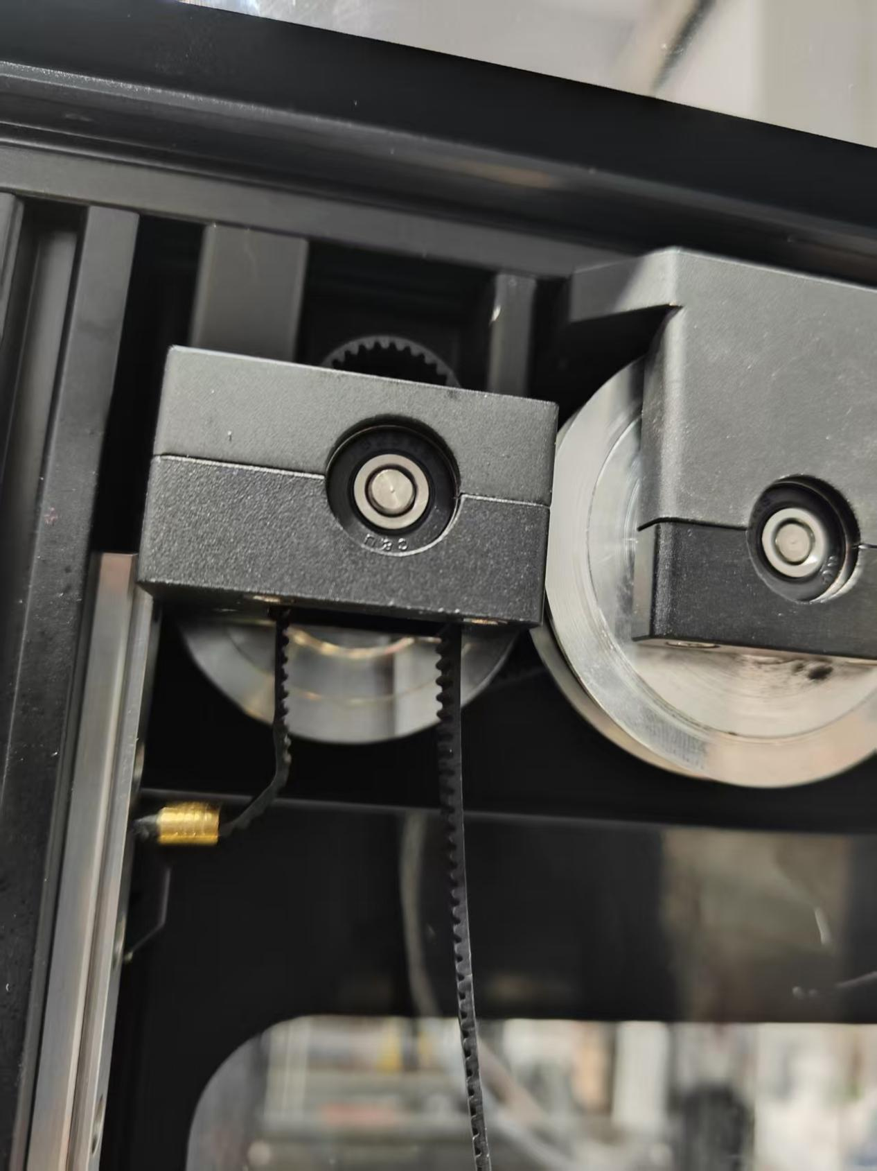
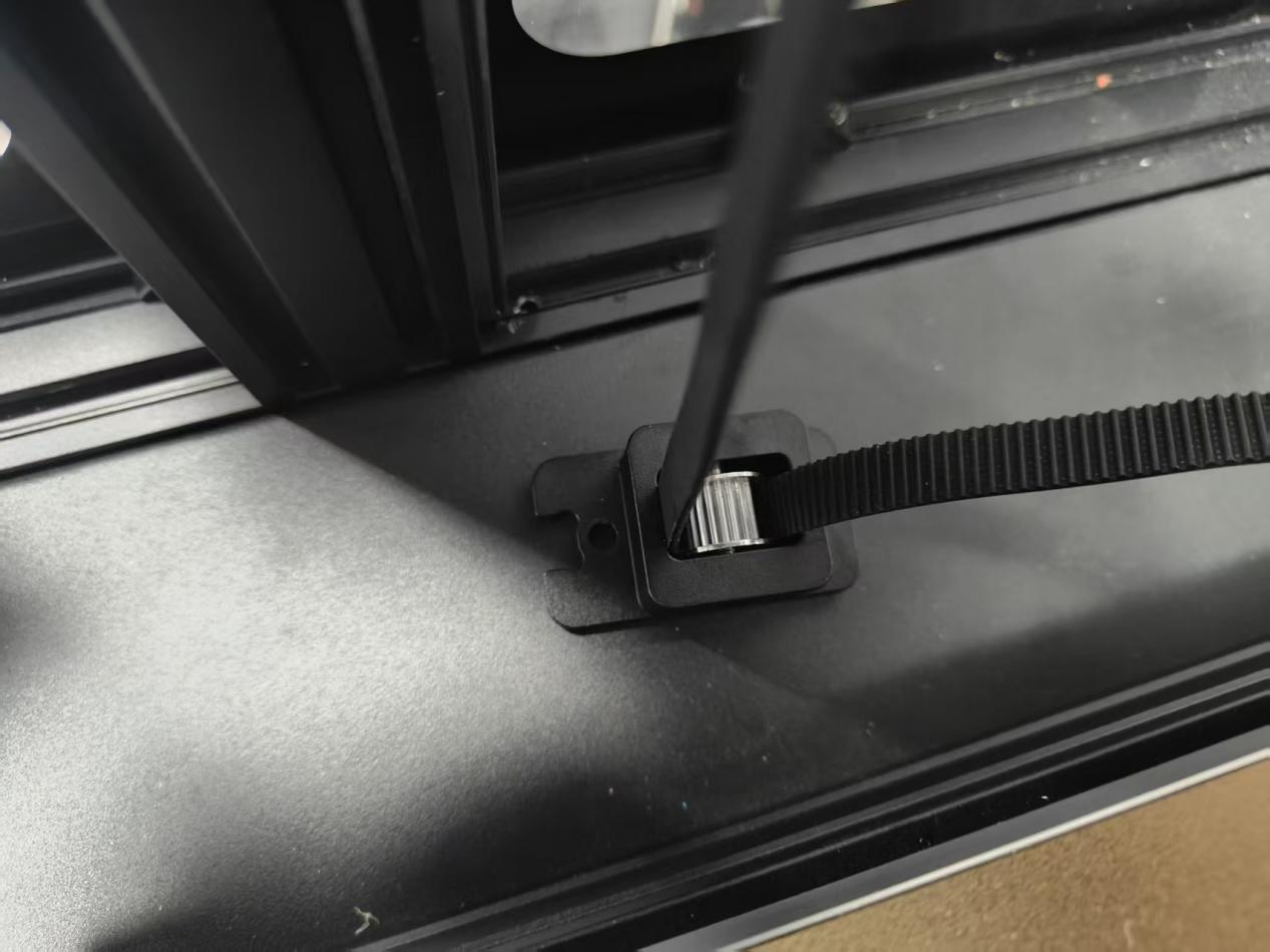
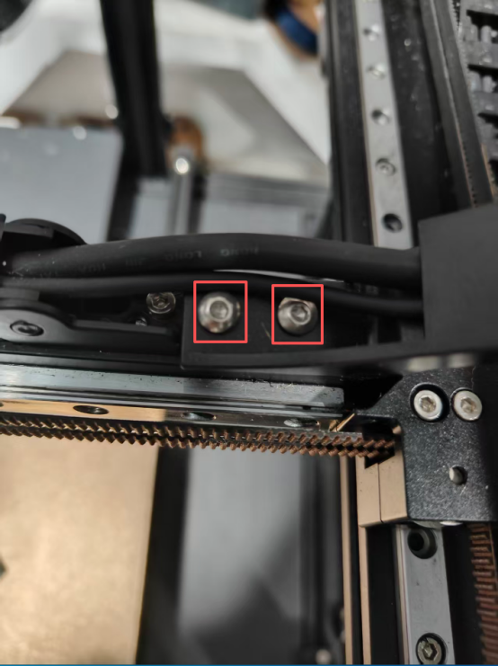
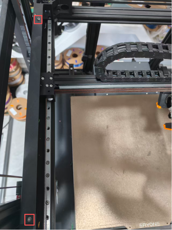
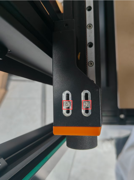
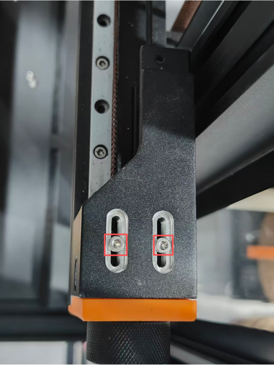
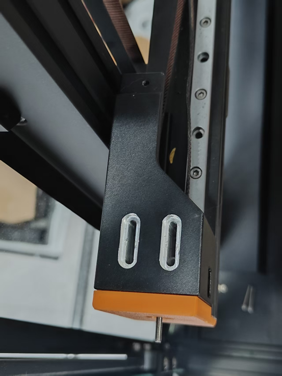
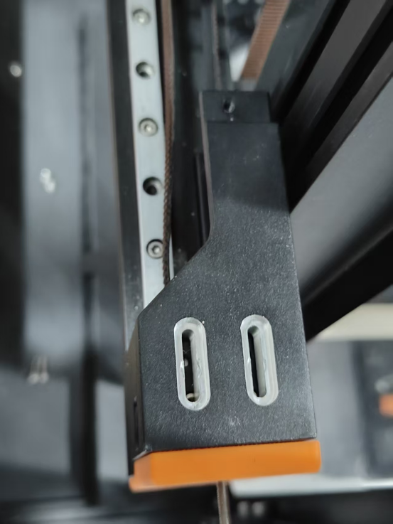
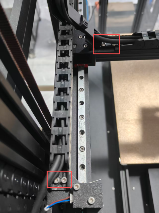
3.Remove the 2 screws from the lower belt holder.
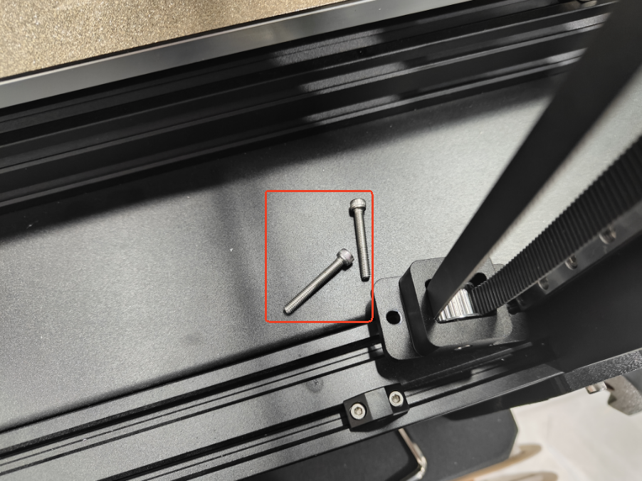
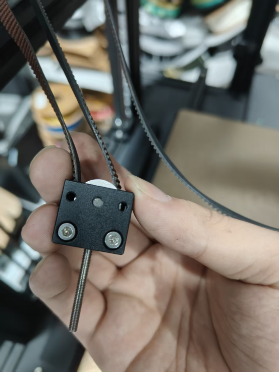
4.Remove the 4 screws from the belt head retainer.
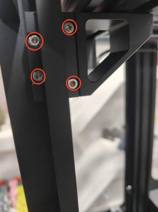
5.Remove the top cover of the belt head retainer and pull out the belt head.
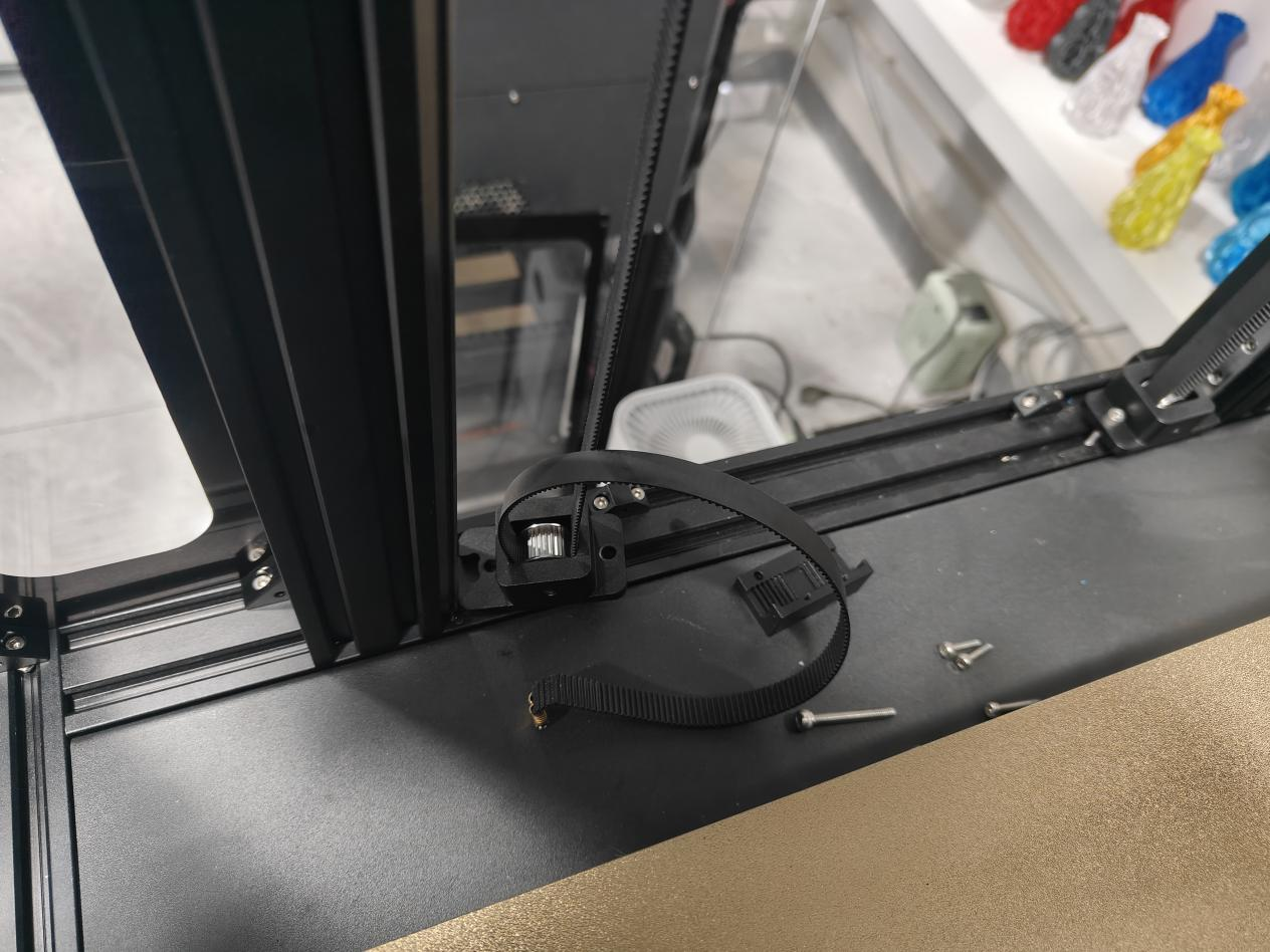
6.Remove the old belt from the top and bottom belt retainers.
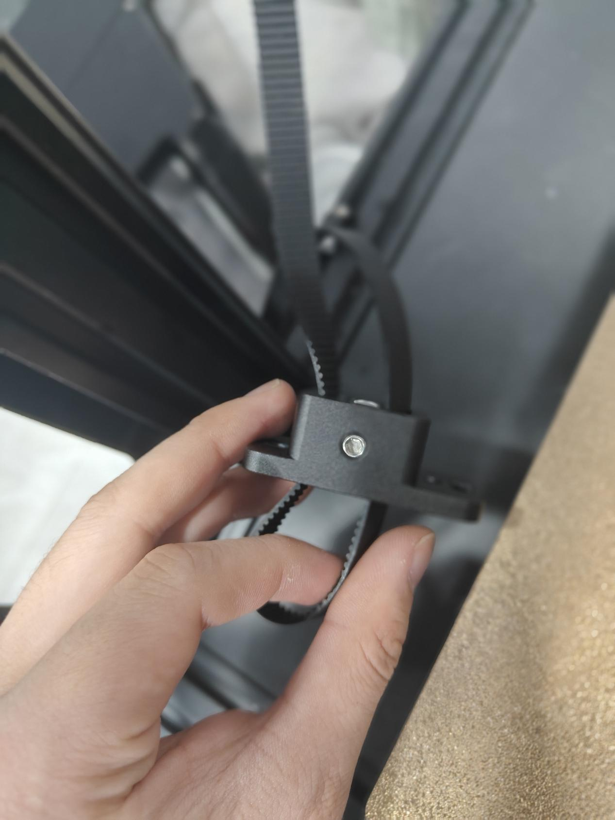
7.Take out a new belt, put the upper and lower ends of the belt back to the belt fixing parts respectively.
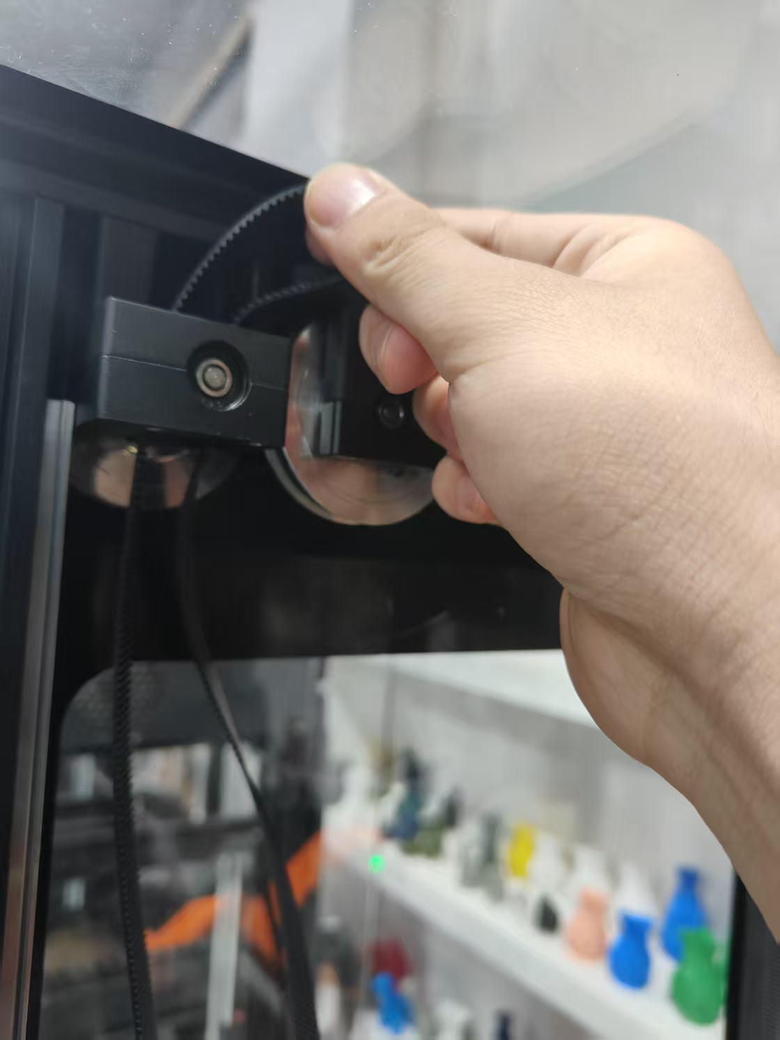
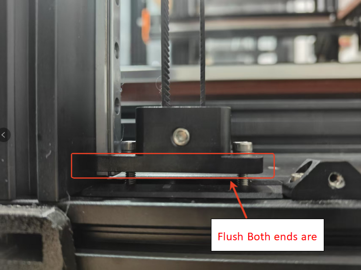
8.Adjust the length, tuck both ends of the belt head back into the buckle and fasten.
9 Screw the lower belt fixture until both ends are flush, squeeze both ends of the belt by hand, and the force between the two ends of the belt is just enough to touch it.
10 Unscrew the four screws of the rubber head fixing piece.
11.Reinstall the acrylic panels.
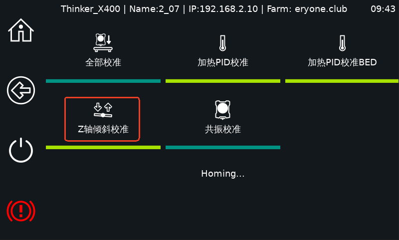
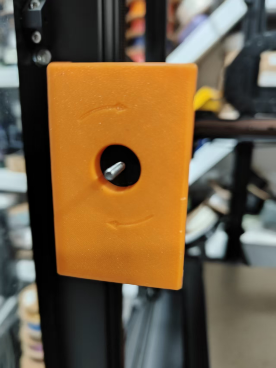
12.Click the Z-axis tilt test.
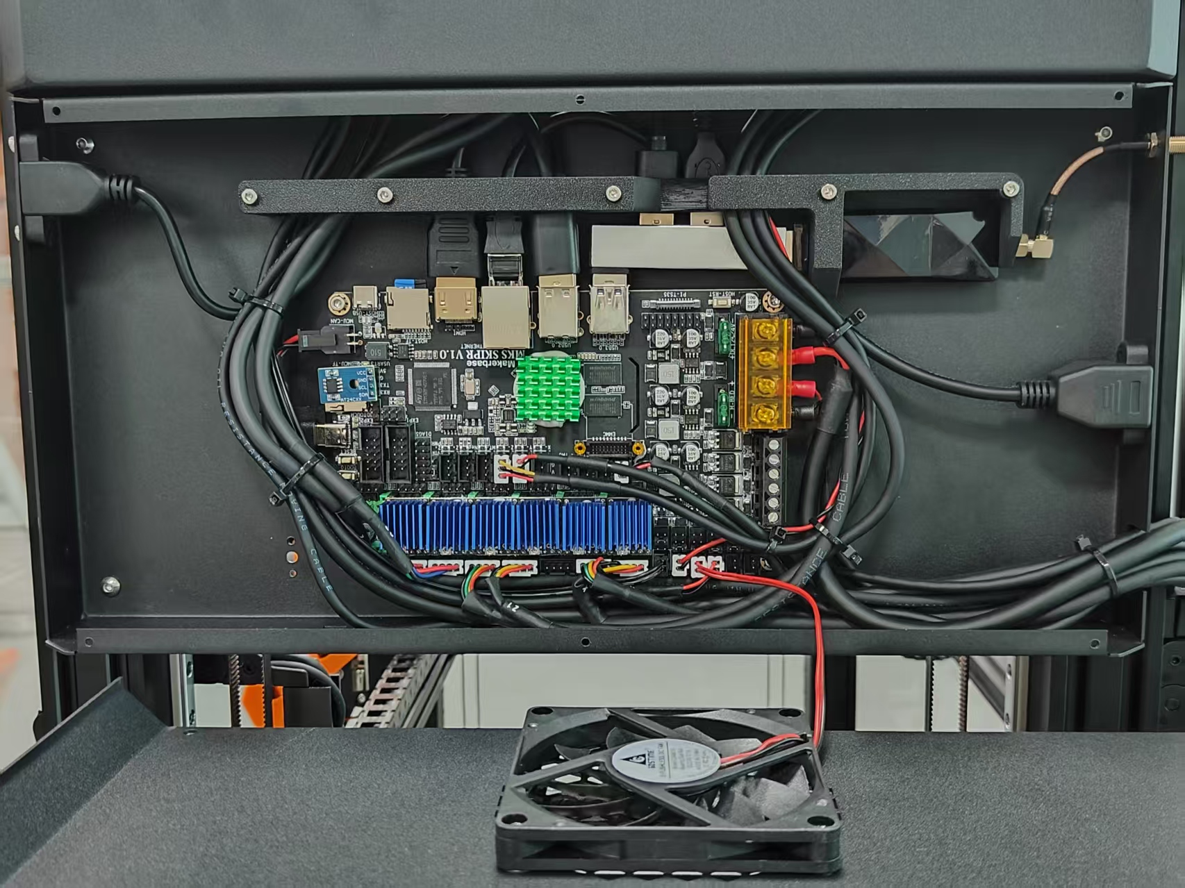
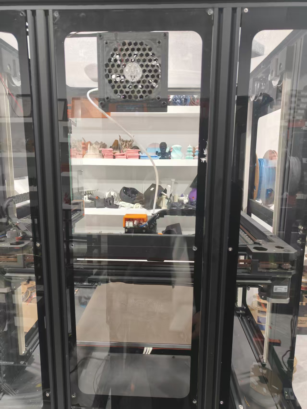
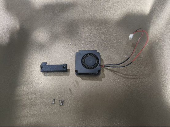
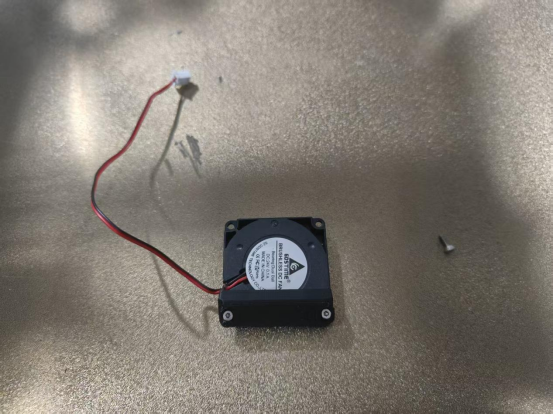
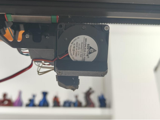
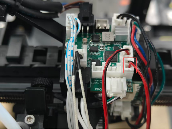
¶ Fan Replacement
Video tutorial:
Replacement steps:
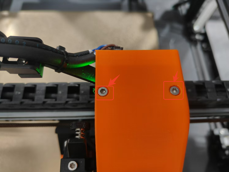
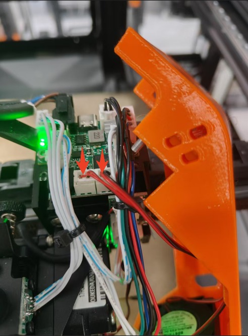
1.Loosen the 2 screws on the extruder bracket cover, slowly pull out the fan cable (caution: do not damage the cable or port) and take out the extruder bracket cover.
2.Remove the 4 screws that hold the fan in place and take the defective fan off.
3.Just put the new fan back in.
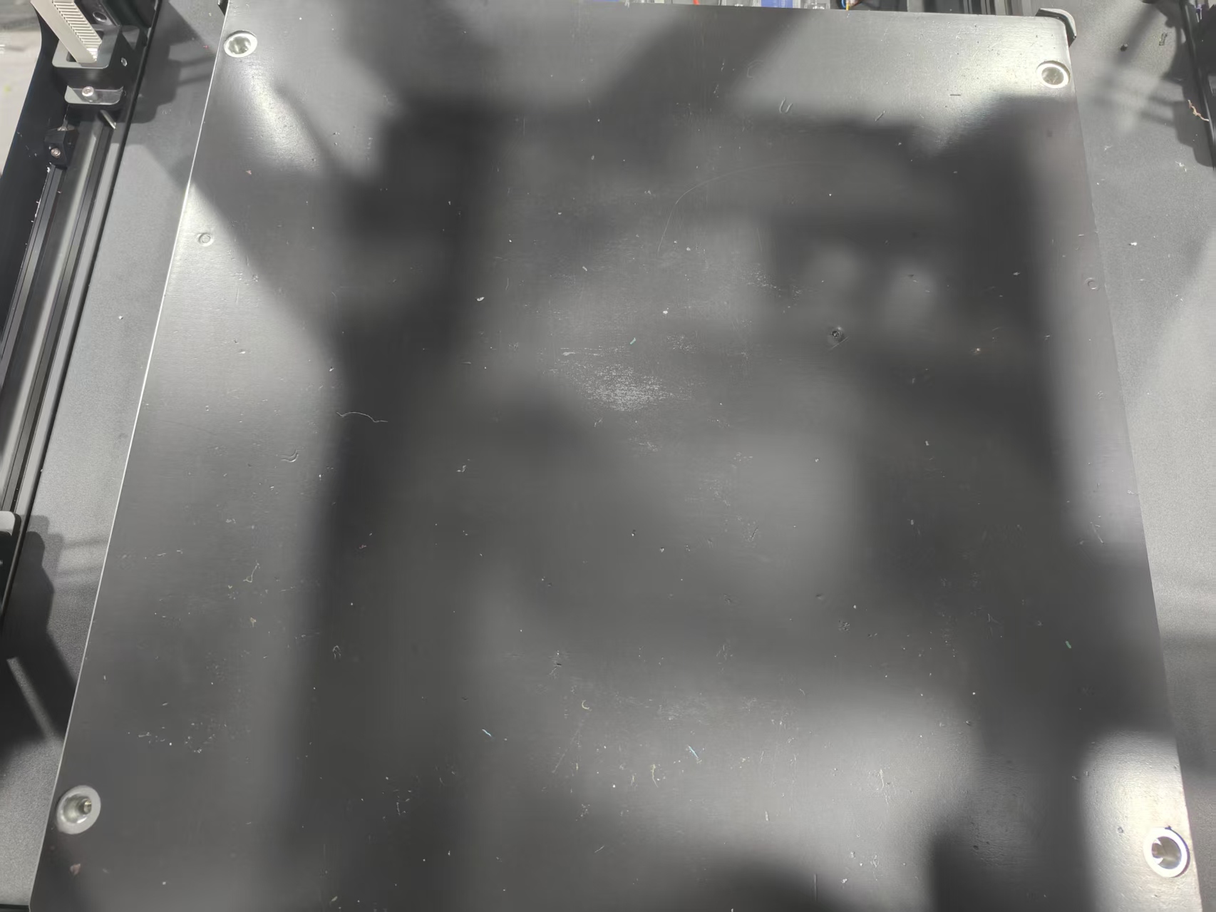
¶ PEI Sheet Replacement
PEI metal plates are filaments and prolonged use can cause some of the PEI on the surface to lose adhesion, which can cause prints to fall off. This is the time to consider a new PEI sheet.Replacement steps.
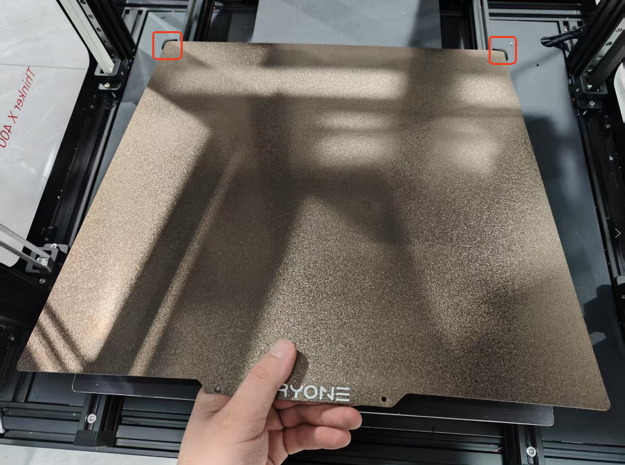
1.Prepare a new PEI sheet.
2.Remove the old PEI sheet.
3.Push the new PEI sheet to the corners of the edge so that the two sides fit perfectly.
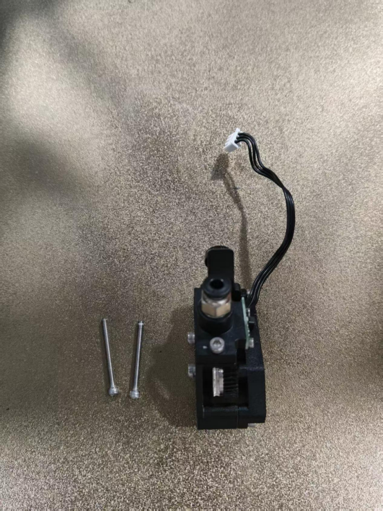
¶ Replacement of motor
Removal steps.
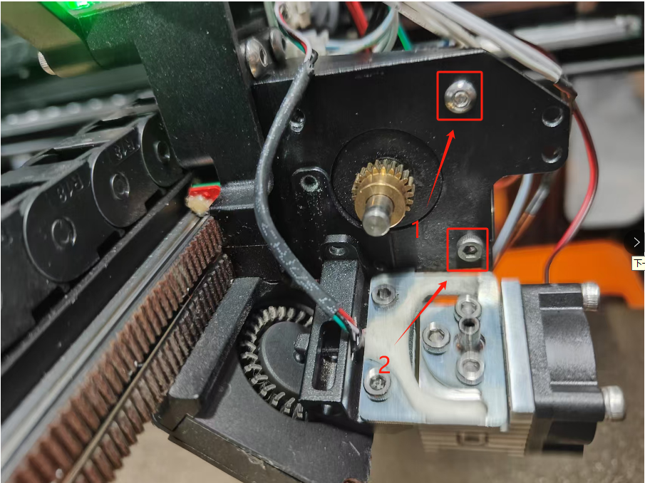
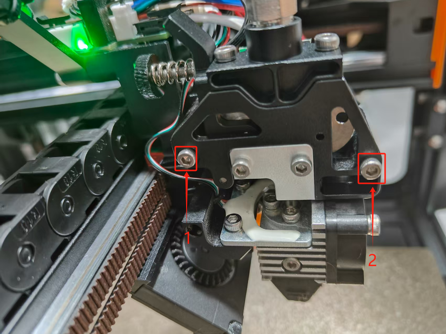
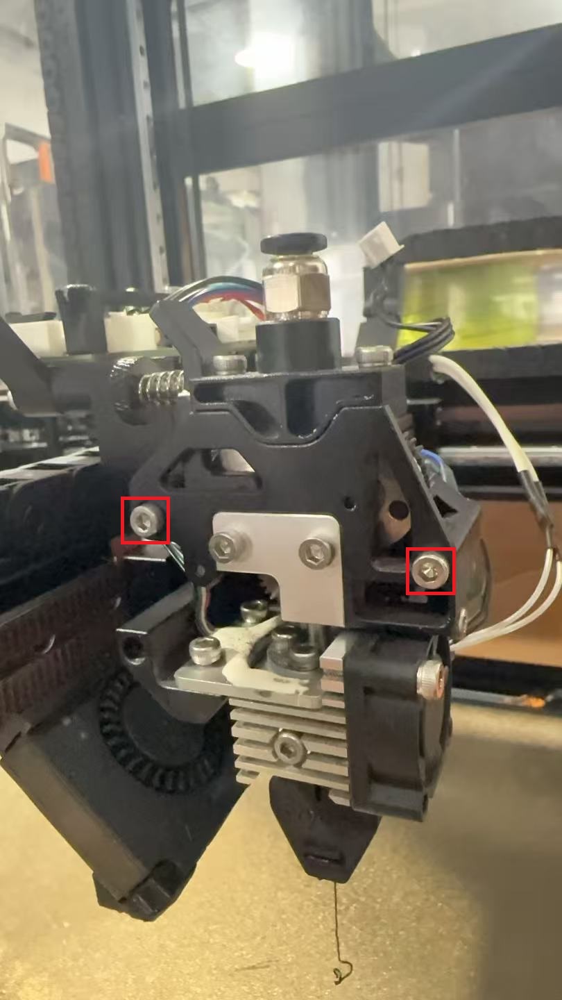
1.Remove the 2 screws on the extruder bracket cover and take away the extruder bracket cover.
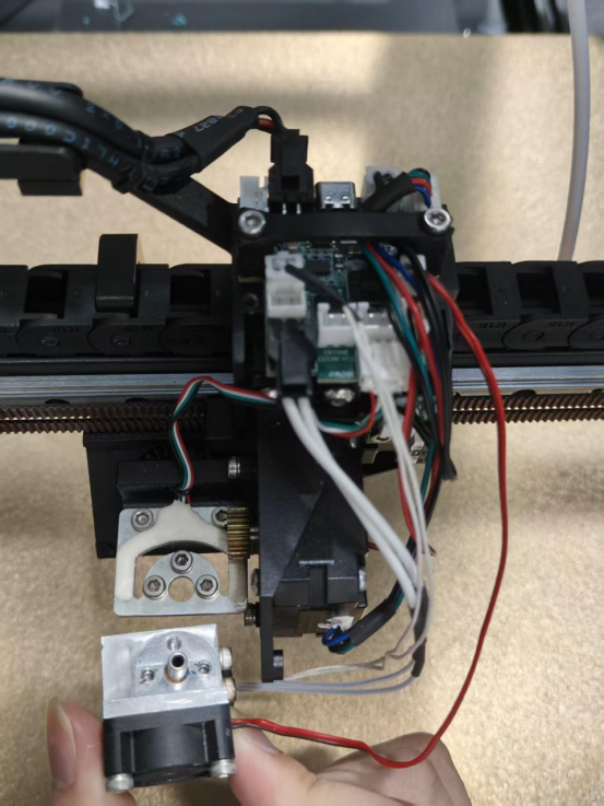
2.Remove the 2 screws on the extruder.
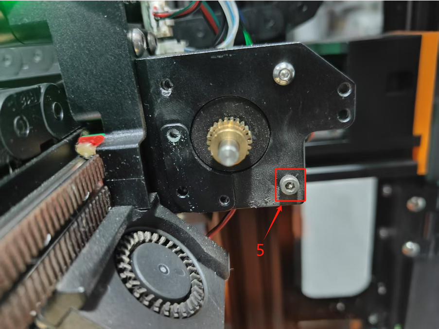
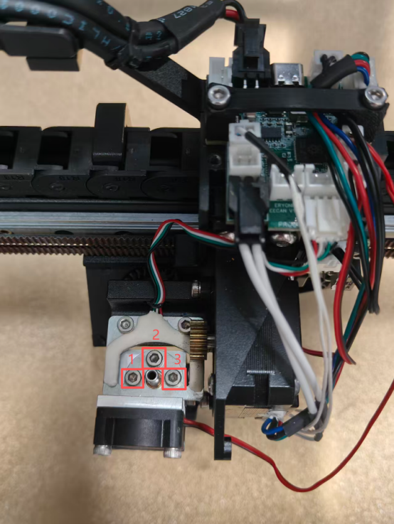
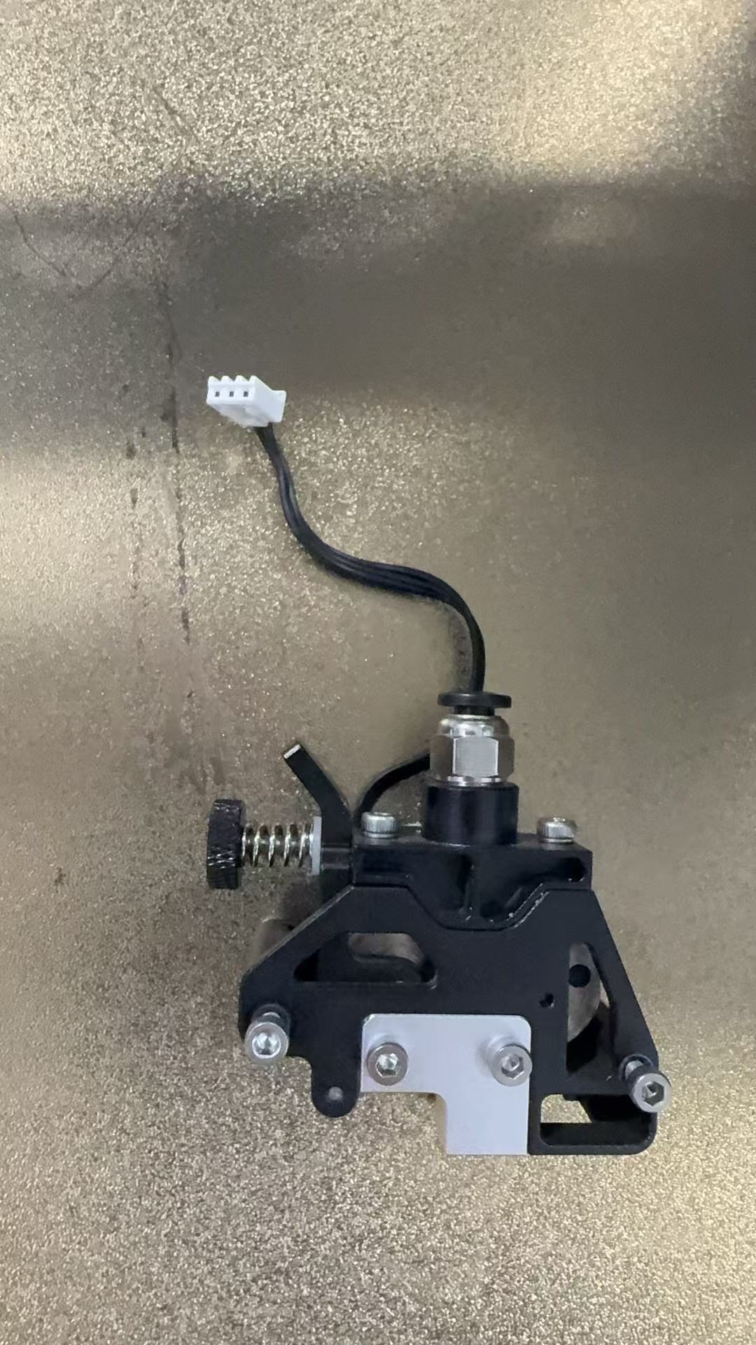
3.Remove the 5 screws that hold the motor in place.
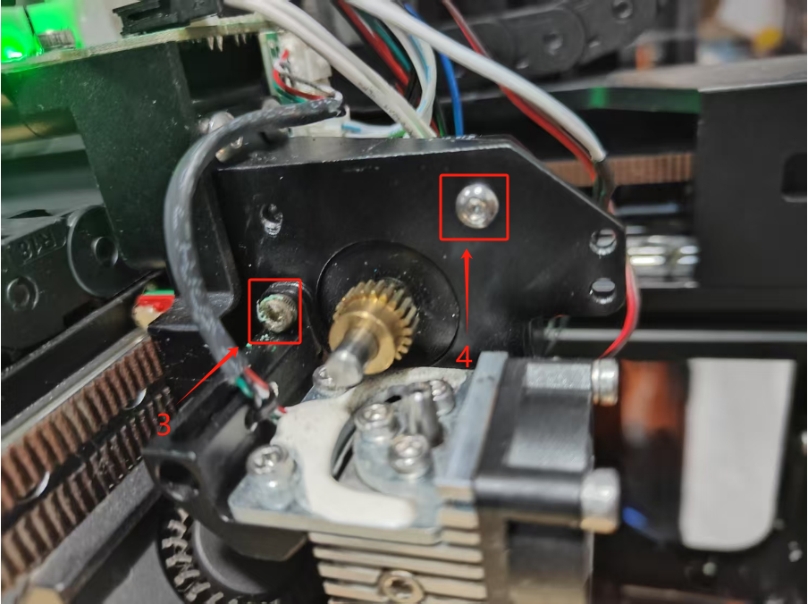
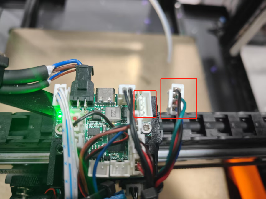
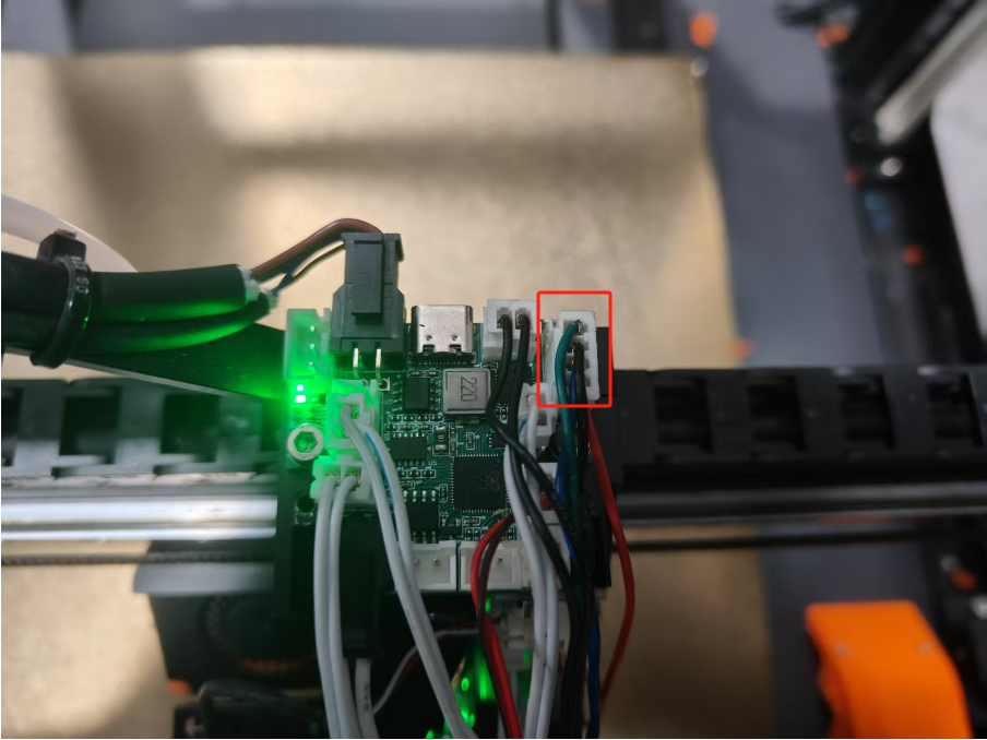
4.Unplug the motor wires from the terminals.
Assembly Steps:
1.Take out the new motor and plug the motor wires back into the terminals.
2.Put the motor through the hole and tighten the 5 screws that secure the motor.
3.Tighten the 2 screws on the extruder.
4.Replace the extruder bracket cover and tighten the 2 screws on the extruder bracket cover.
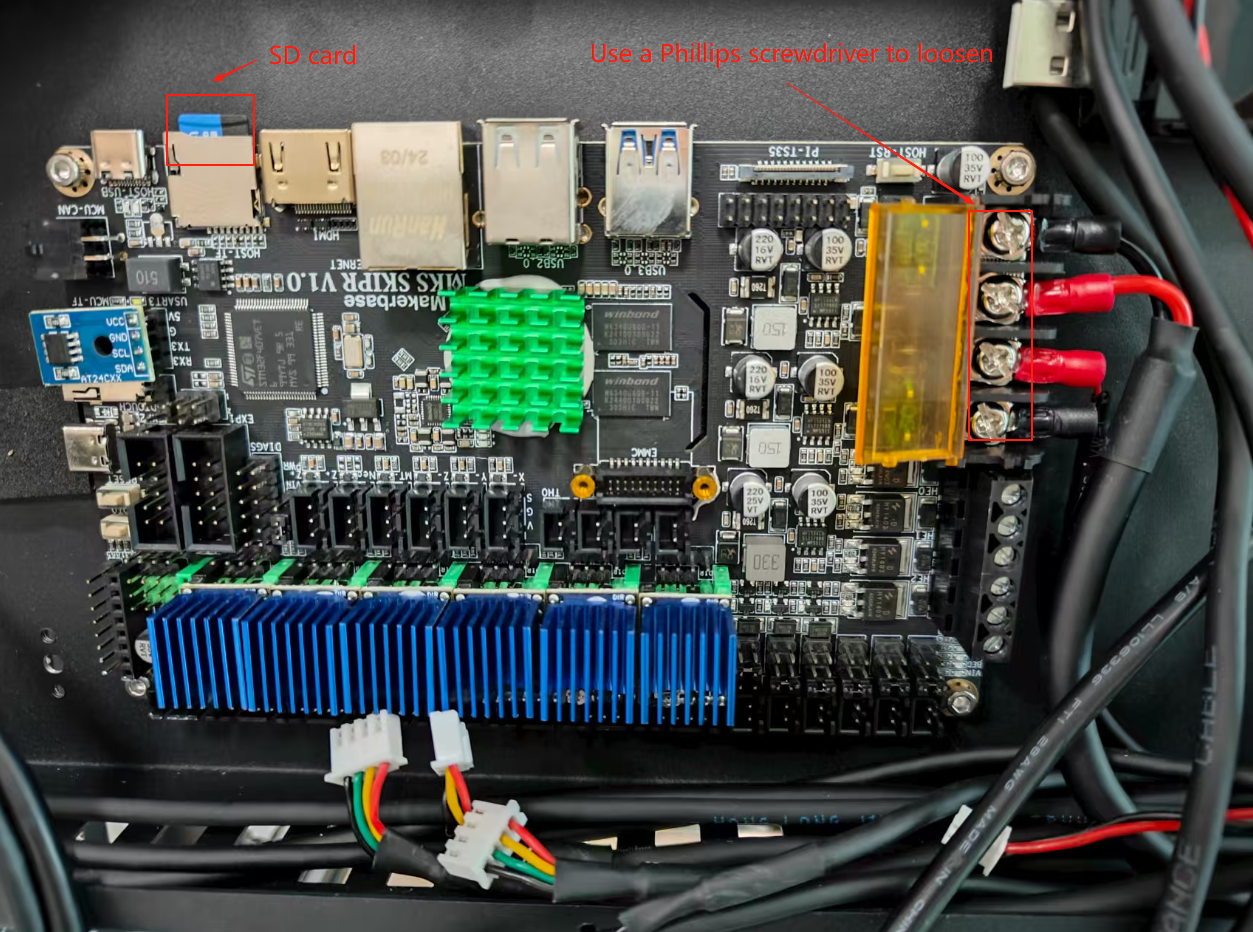
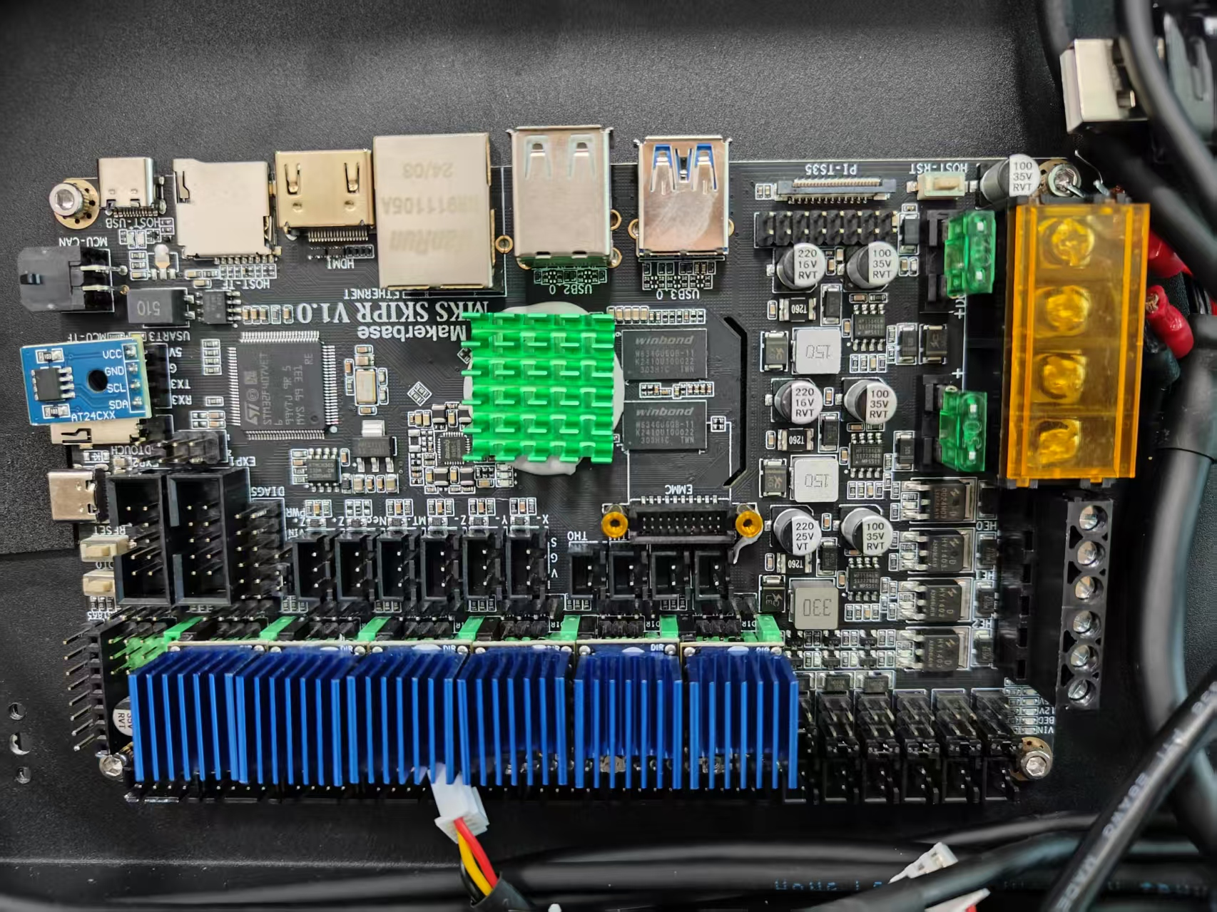
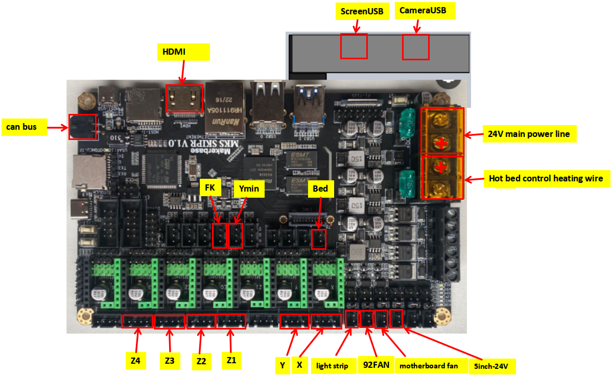
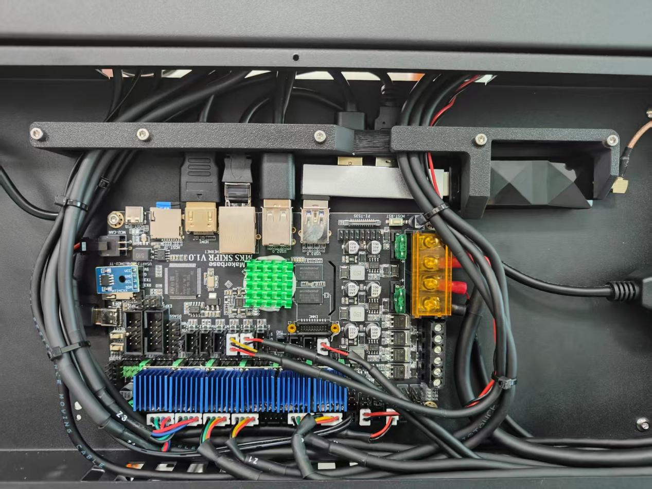
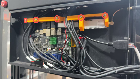
¶ MKS SKIPR Klipper All-in-One Mainboard Assembly Guide
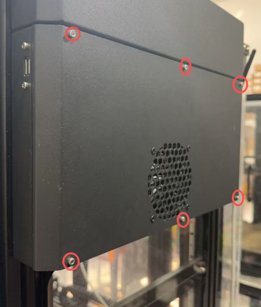
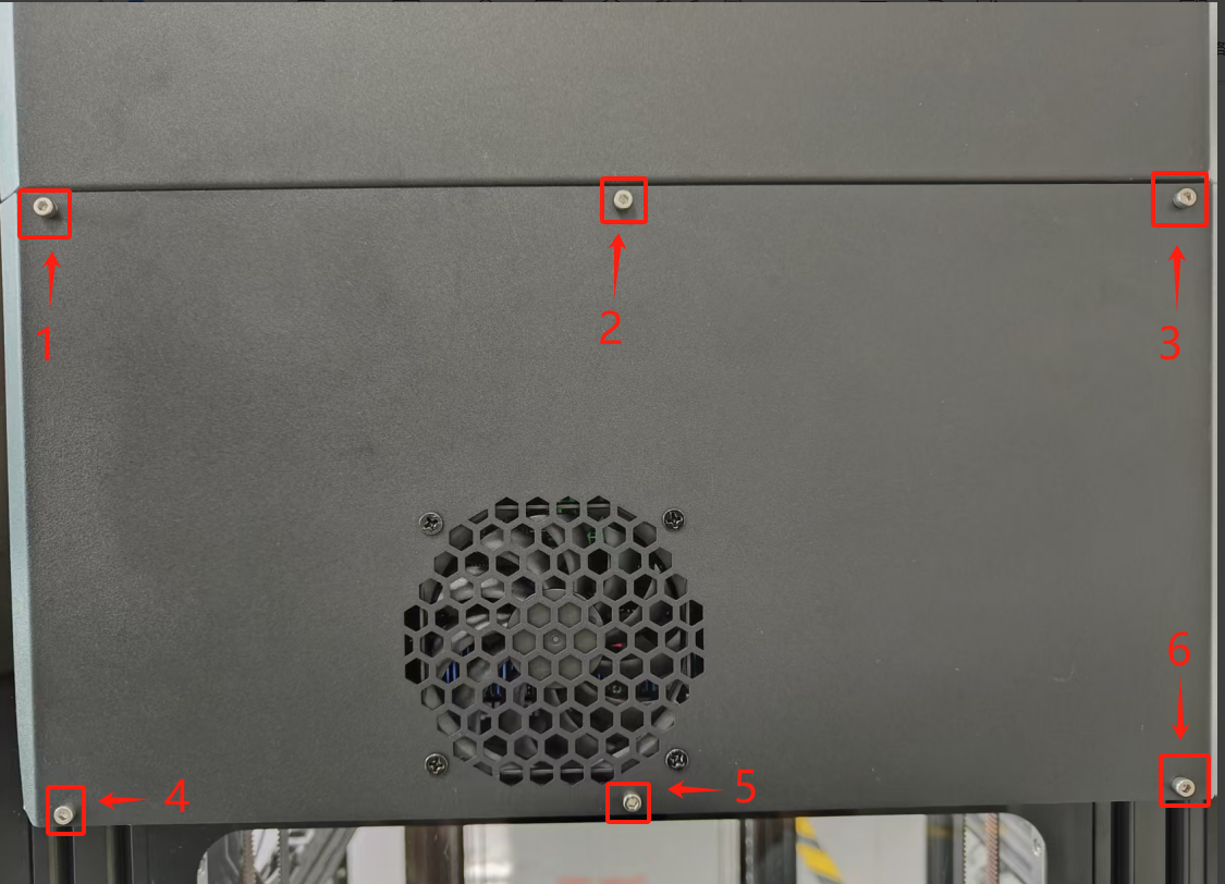
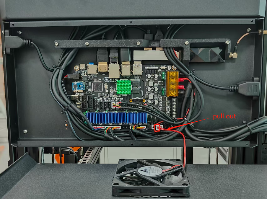
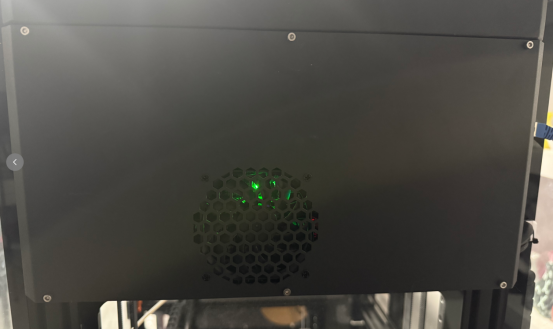
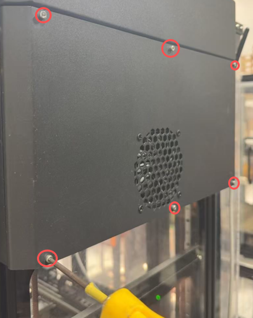
1.Using a 2.5mm hex key, remove the six mounting screws securing the right-side motherboard cover assembly, then disconnect the cooling fan cable.
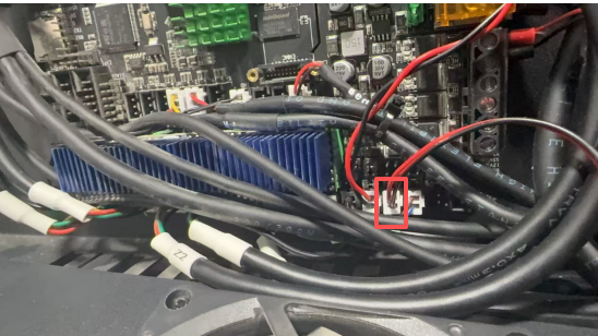
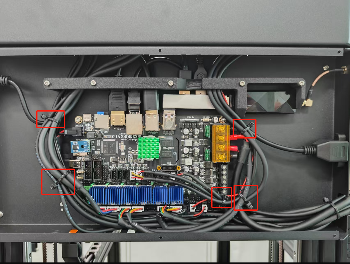
2.Remove Cable Ties.
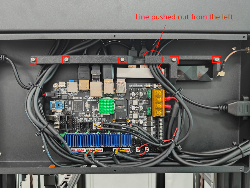
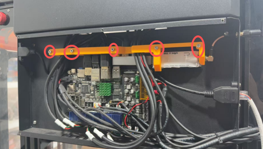
3.Use a 2.5mm hexagonal wrench to remove the 5 screws on the wiring harness blocker and remove the wiring harness blocker.
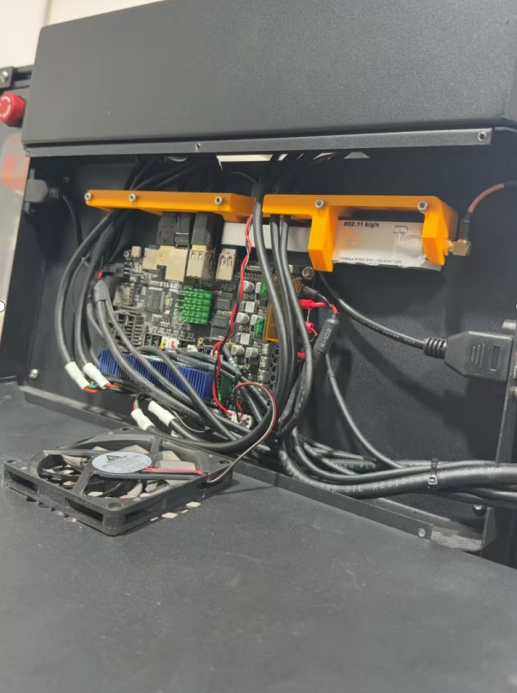
4.Disconnect all cables, expansion modules, and remove the SD card from the old motherboard.
5.Using a 2.5mm hex key, remove the four mounting screws securing the legacy motherboard, then carefully extract the board from its housing.
6.Install the new motherboard and secure with screws.
7.Reconnect all cables, expansion dock, and SD card to the new motherboard.
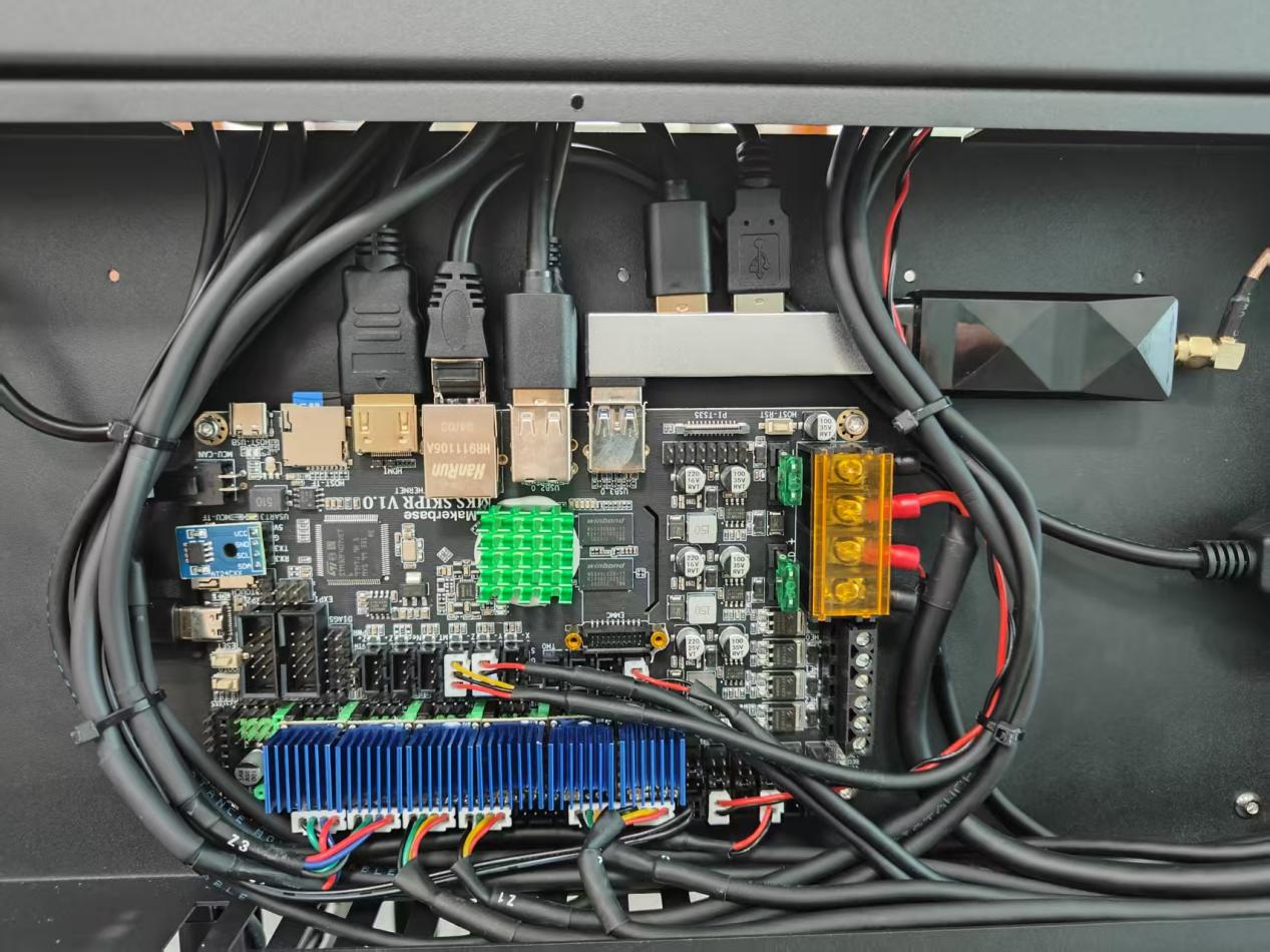
8.Reinstall the Wiring Harness Bracket.
9.Reinstall Cooling Fan and Motherboard Cover.
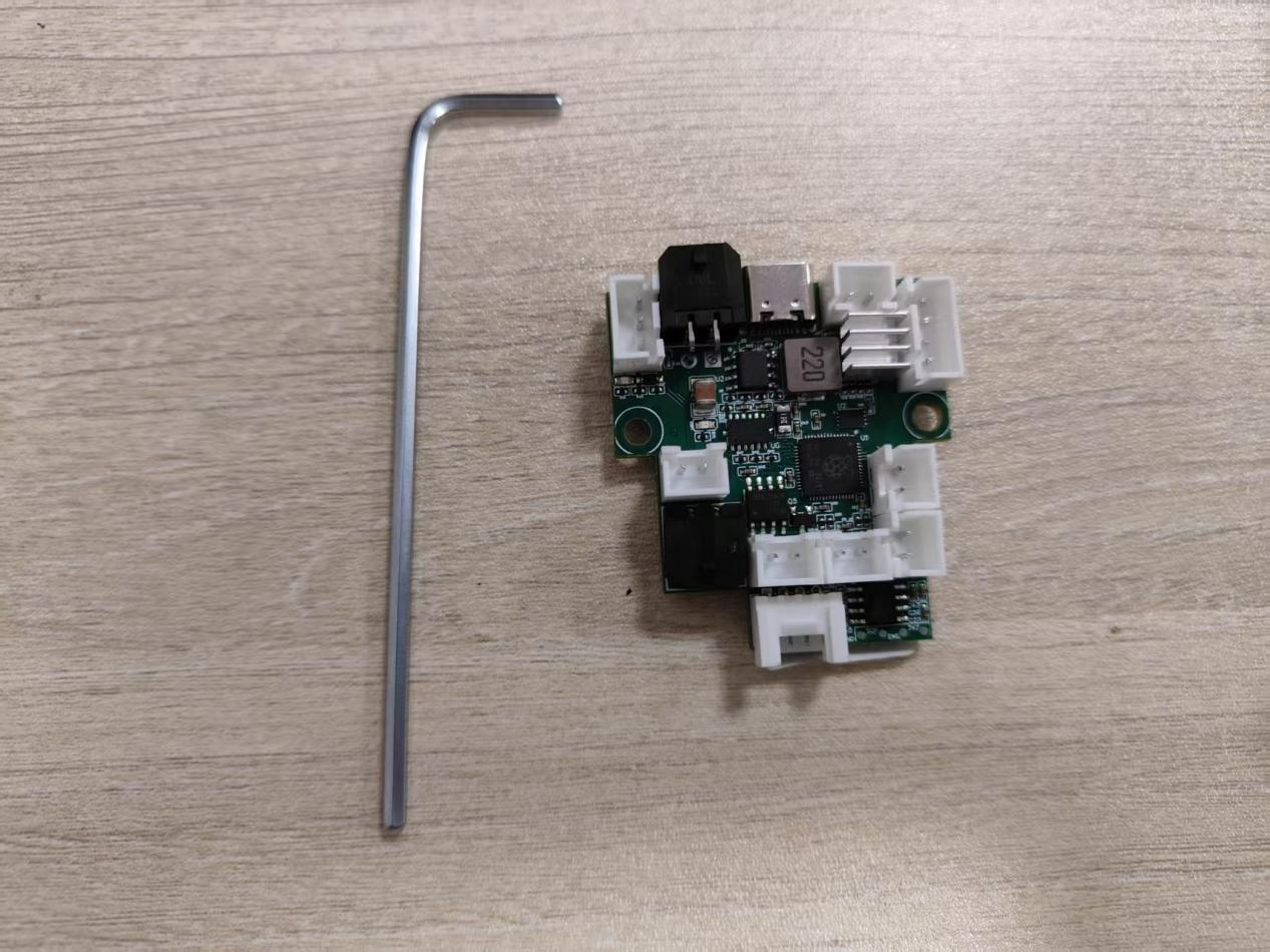
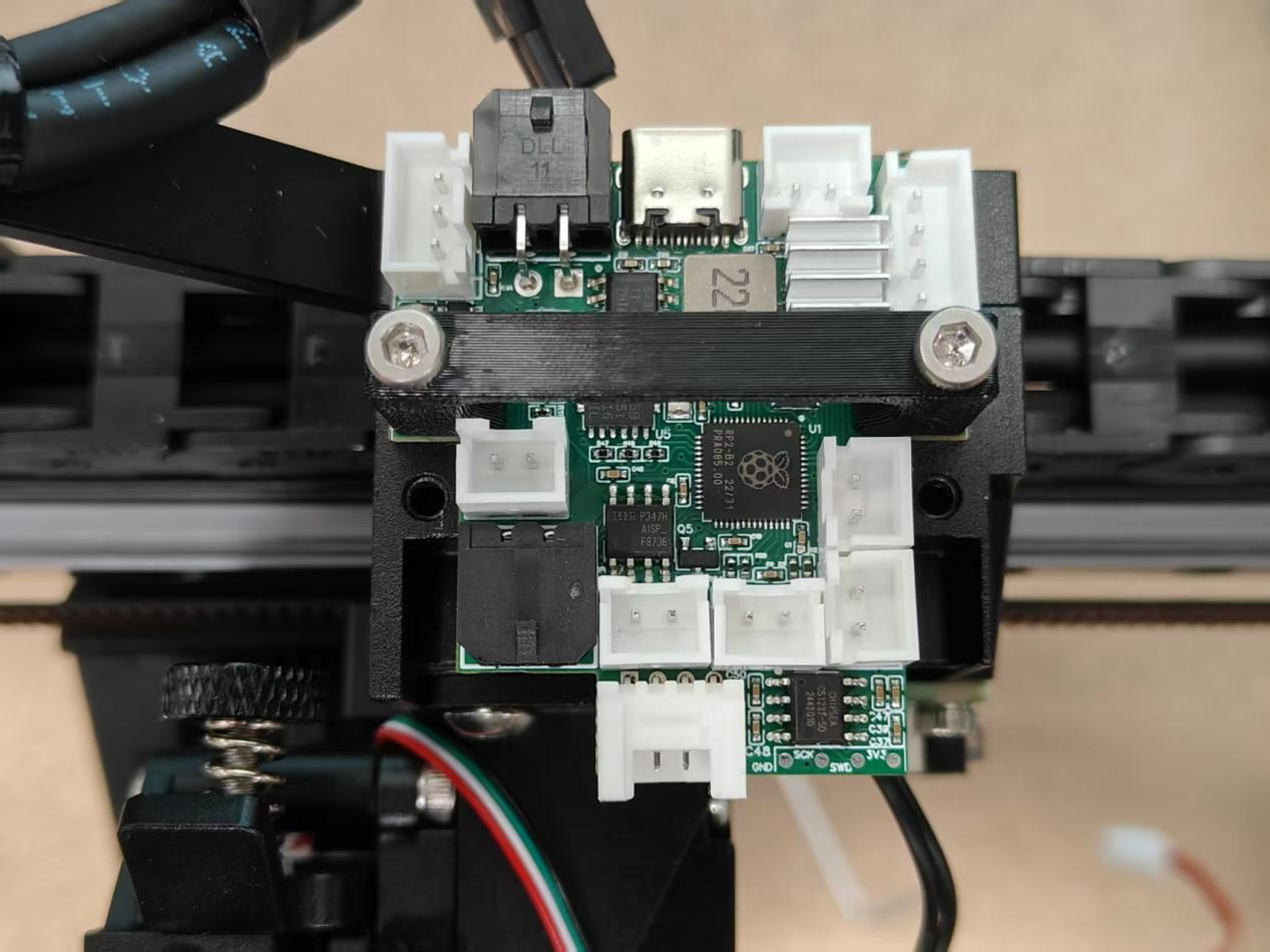
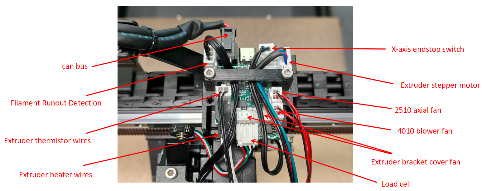
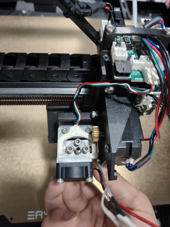
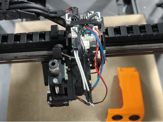
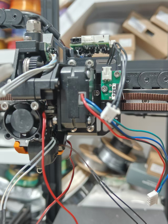
¶ Canbus motherboard installation
Video tutorial:
1.Prepare a 2.5mm hex key and a CAN bus mainboard.
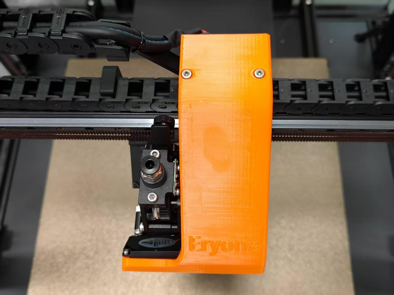
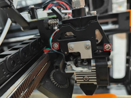
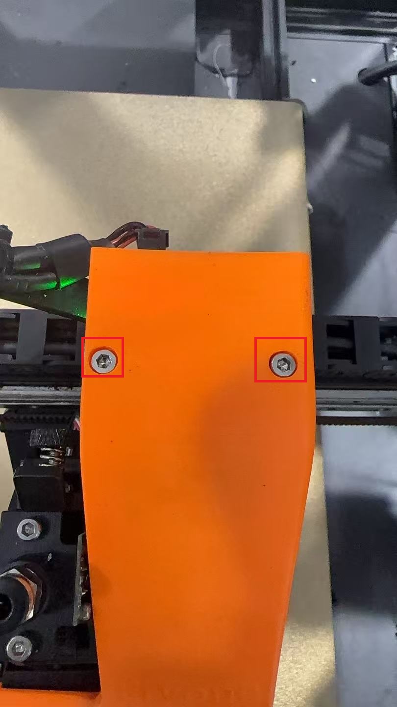
2.Using a 2.5mm hex wrench, detach the extruder mounting bracket cover and its screws, placing them aside.
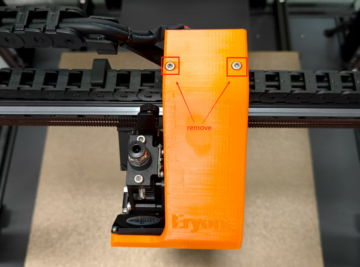
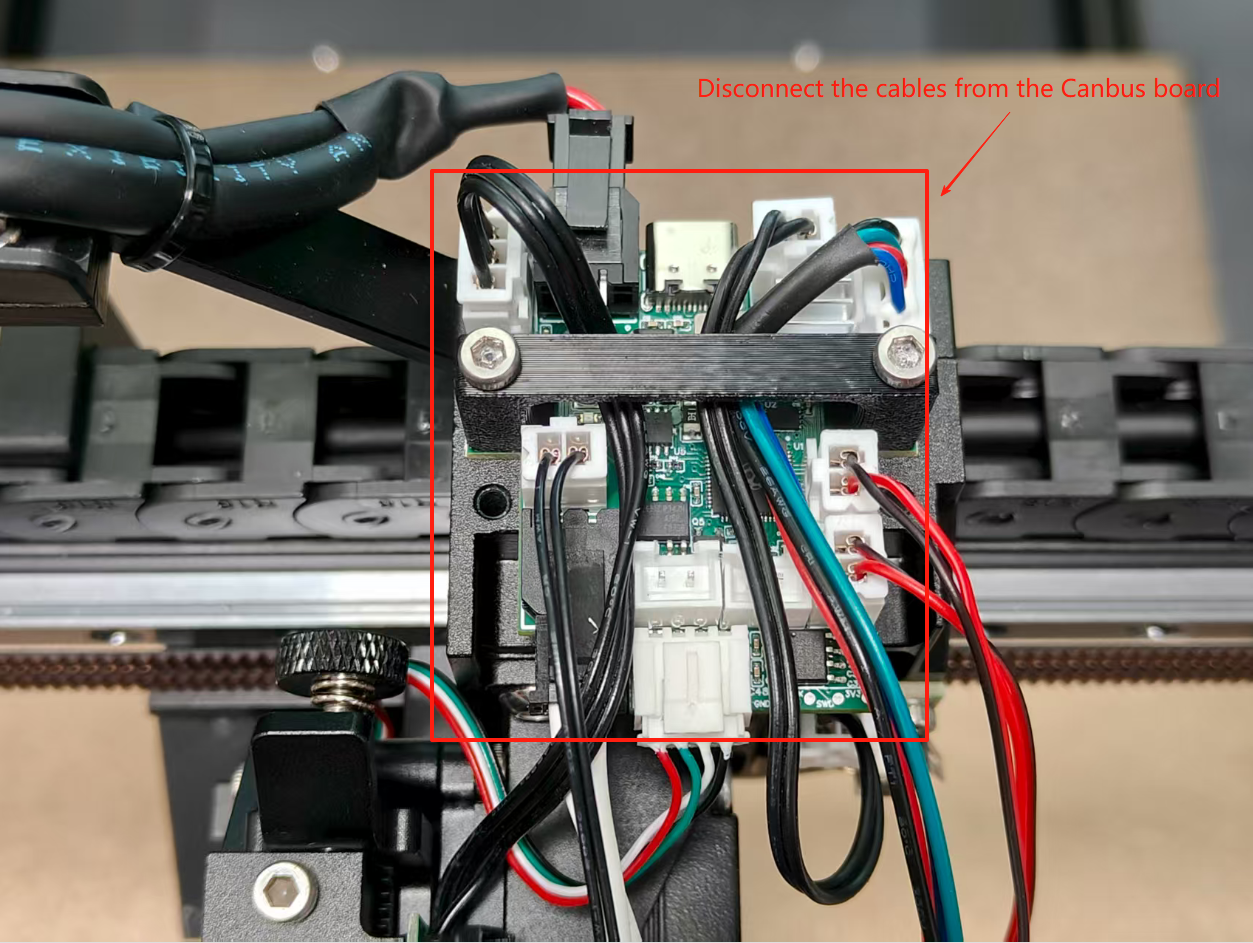
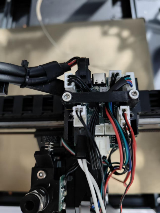
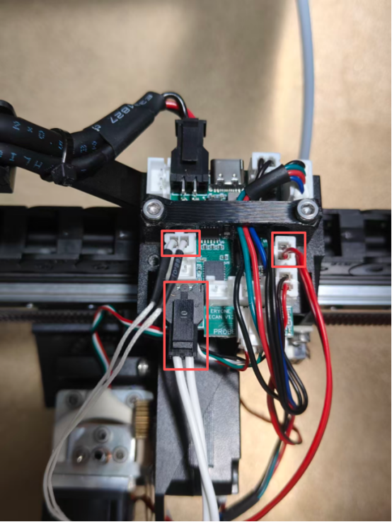
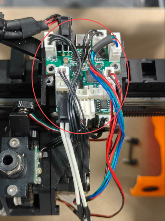
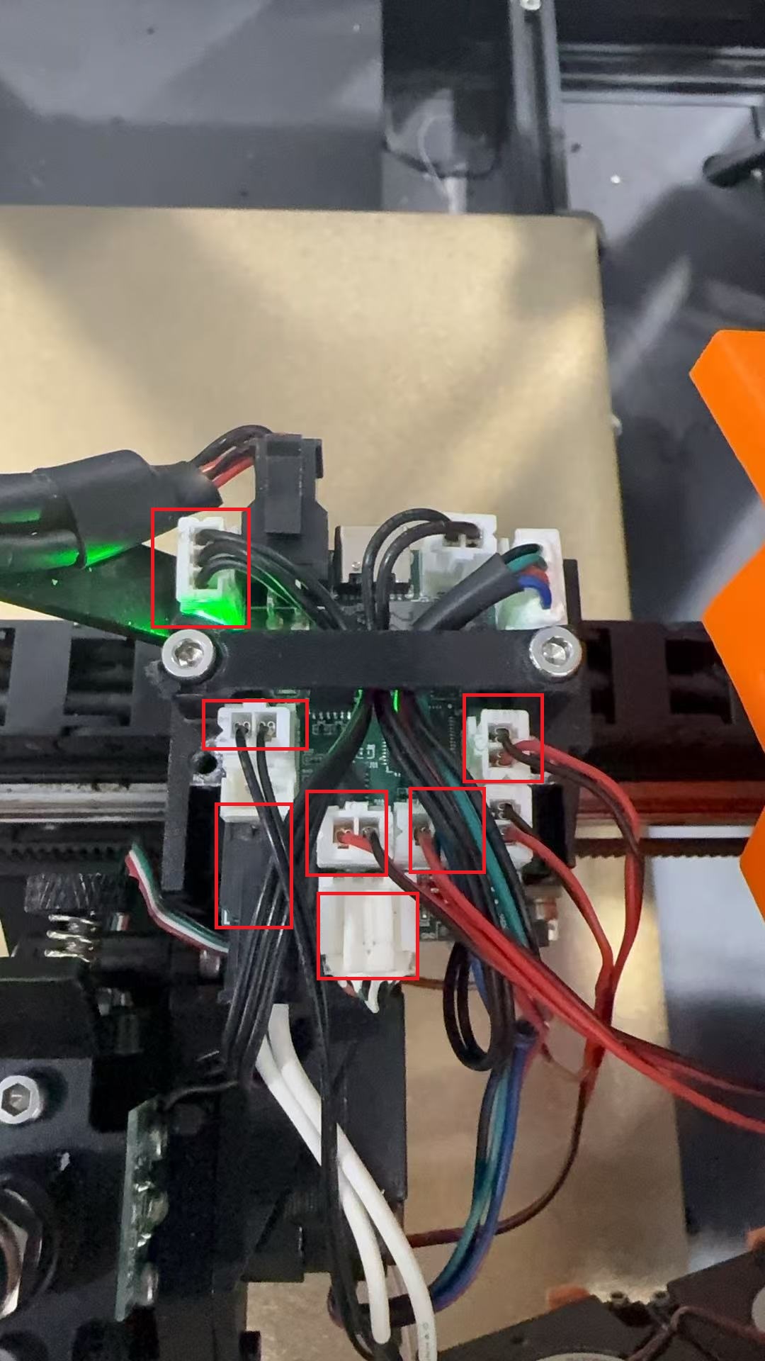
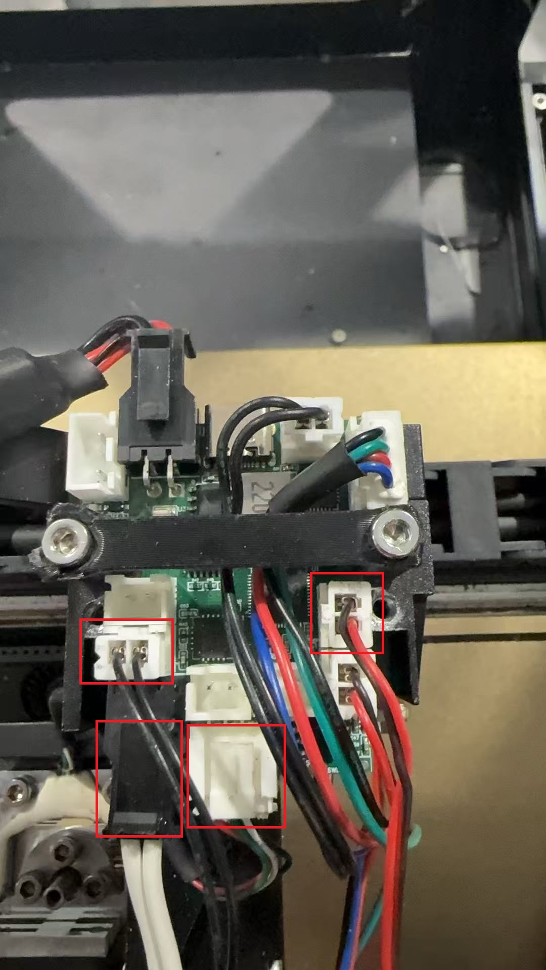
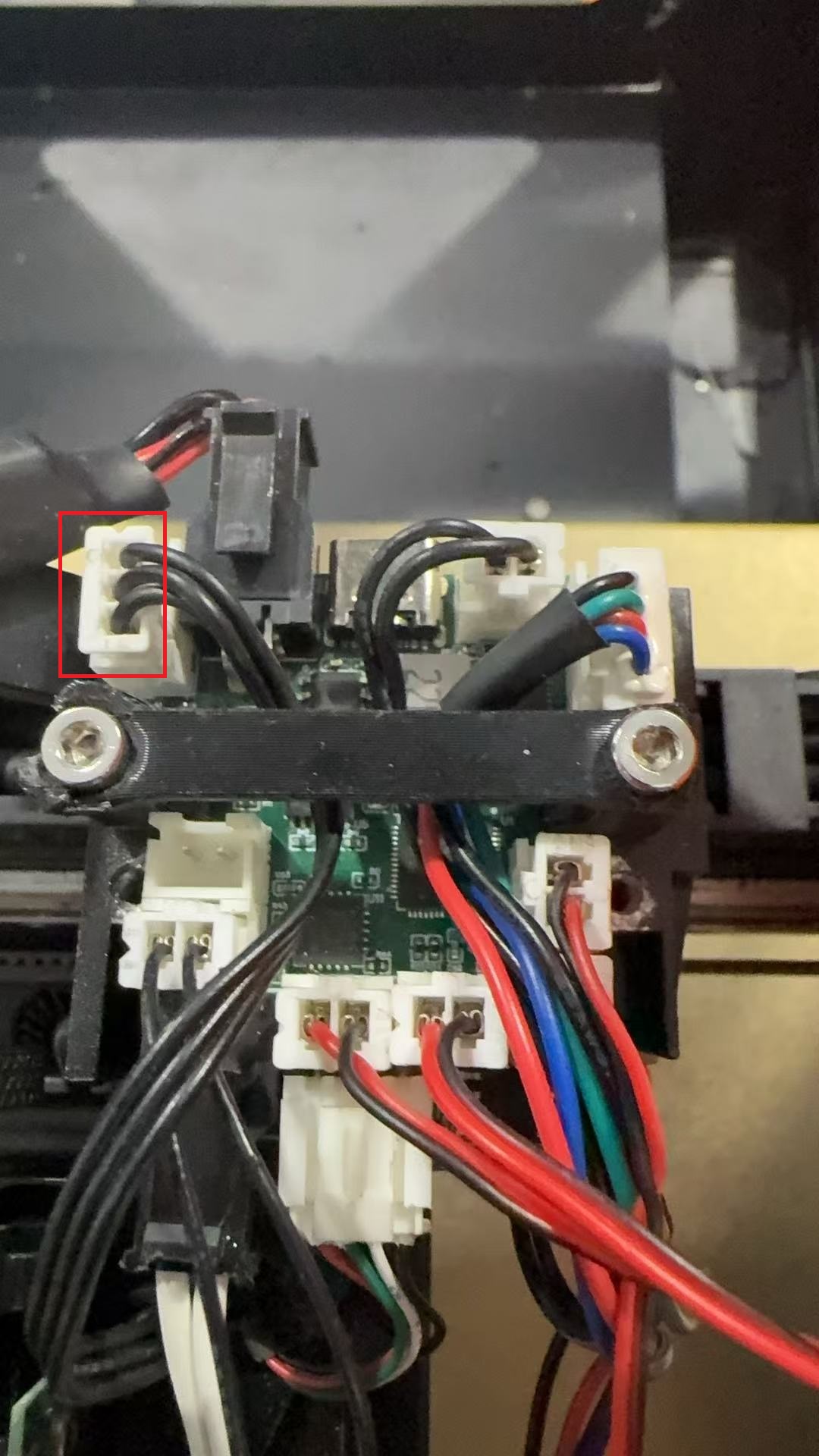
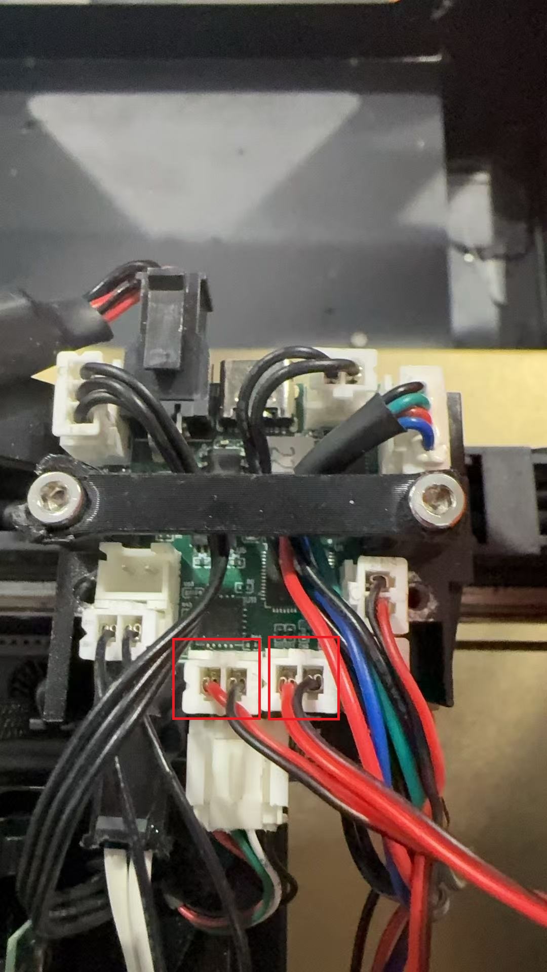
3.Disconnect all cables from the old extruder control board.
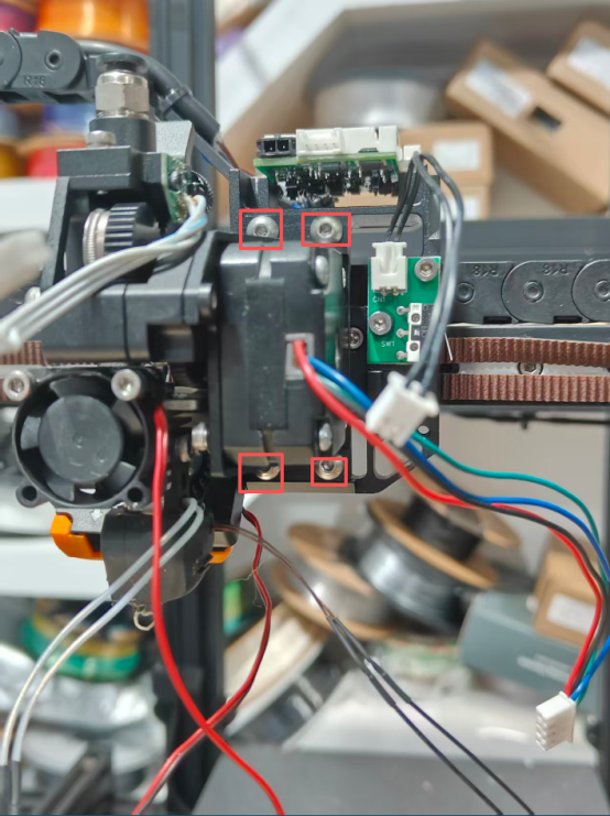
4.Using a 2.5mm hex key, remove the two screws from the Canbus cable bracket and extract the old Canbus mainboard.

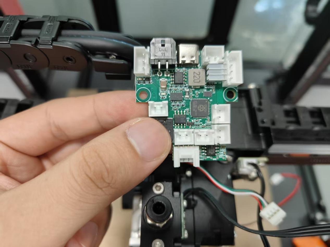
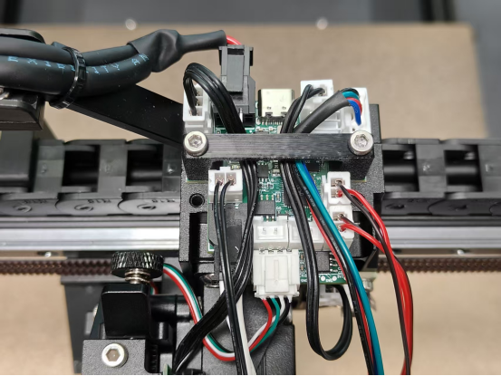
5.Install the new Canbus mainboard and secure it with the Canbus cable bracket.
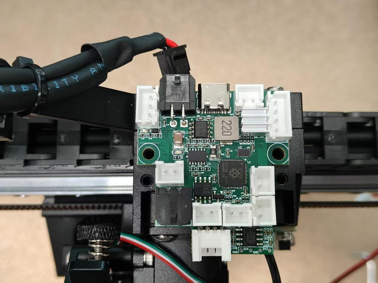
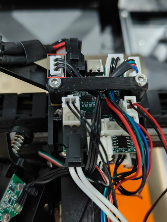
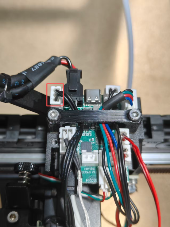
6.Reconnect all cables to the extruder.
7.Install the extruder bracket cover.
8.Inspect the CAN Bus Adapter Board
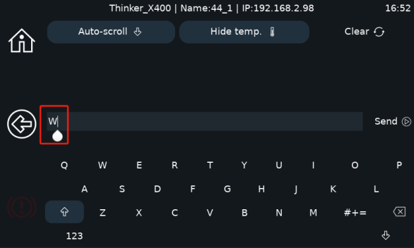
8.1 After powering on, click the console button.
8.2 Enter a capital letter "W" in the console. Two UUID numbers should appear (if only one UUID appears, power off and re-enter "W").
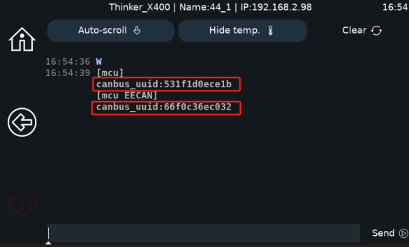
8.3 Power off and restart the printer. The machine will successfully enter the main page.
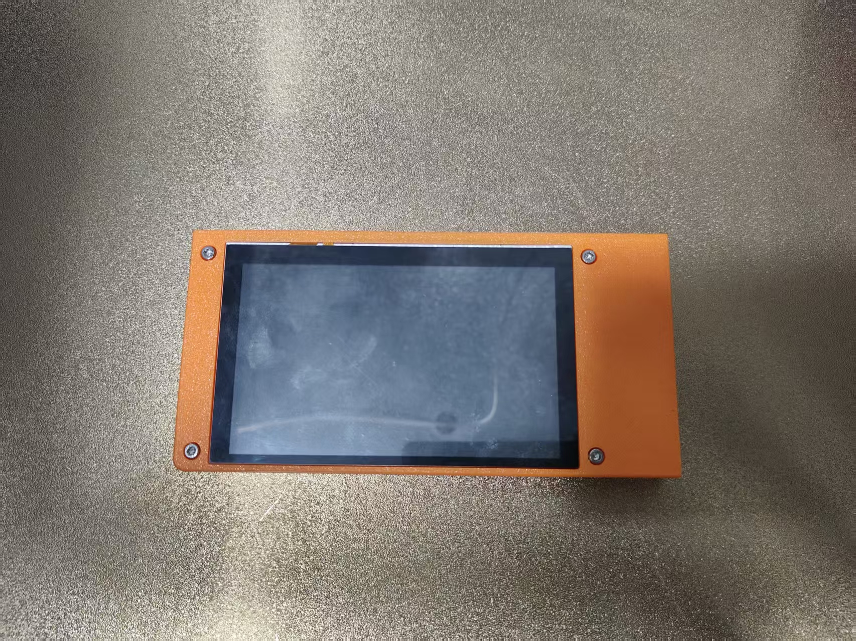
¶ Replacing the Thinker X400 Screen
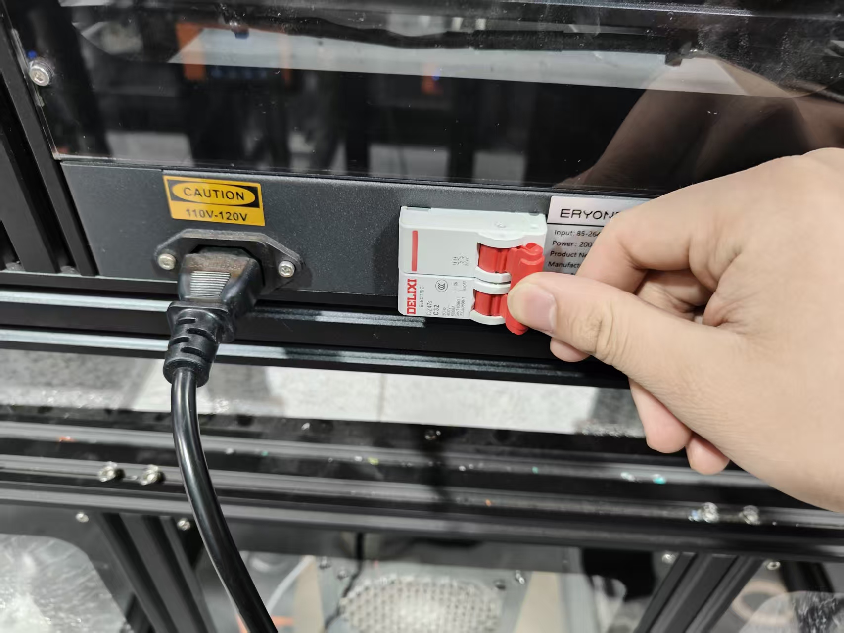
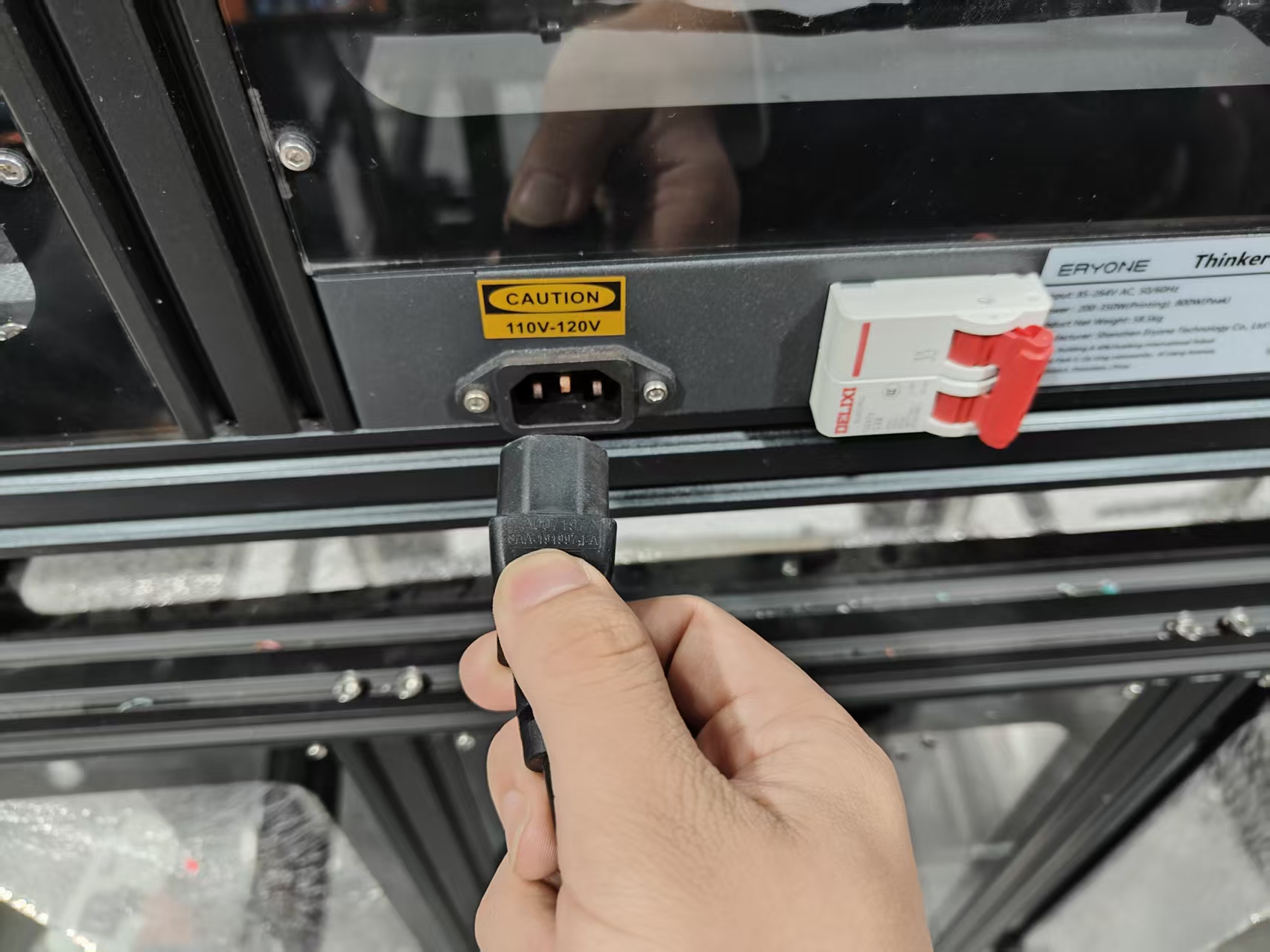
1.Power off the Thinker X400 (ensure it is completely shut down and disconnected from power).
2.Remove the 3 screws securing the screen assembly.
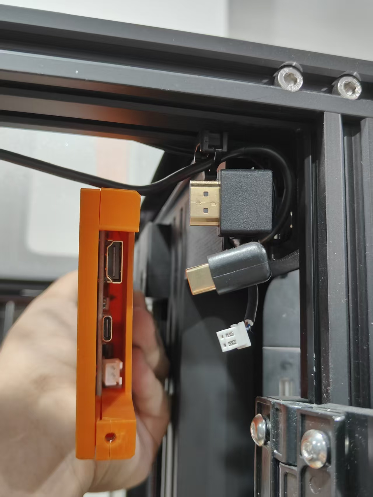
3.Unplug the 3 cables connected to the screen, and safely place the screen assembly aside.

4.Remove the 4 screws from the screen top cover, then take out the old screen.
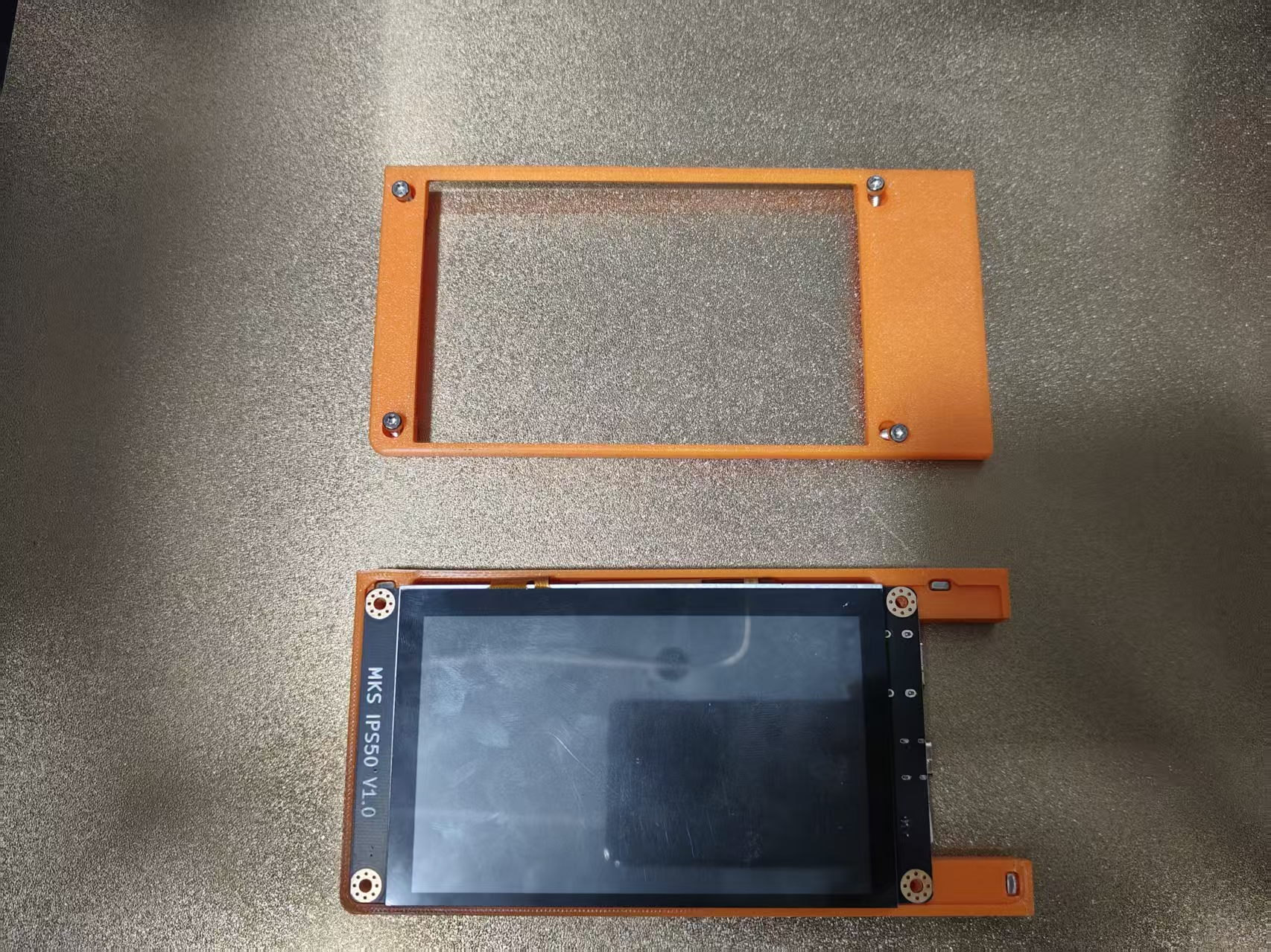
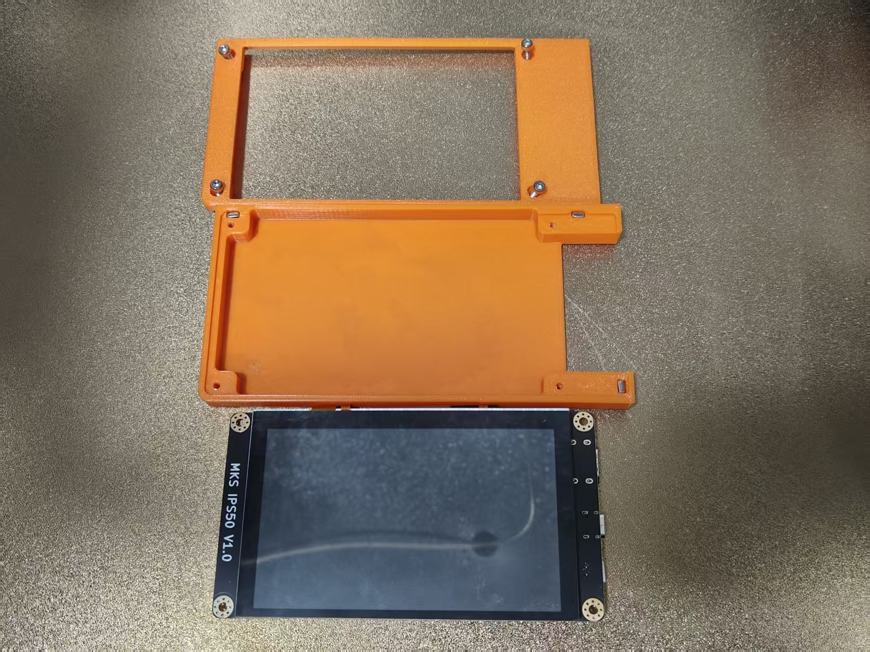
Note: Be careful with the 3 nuts in the screen base; avoid dropping and losing them
5.Place the new Thinker X400 screen into position and close the cover.
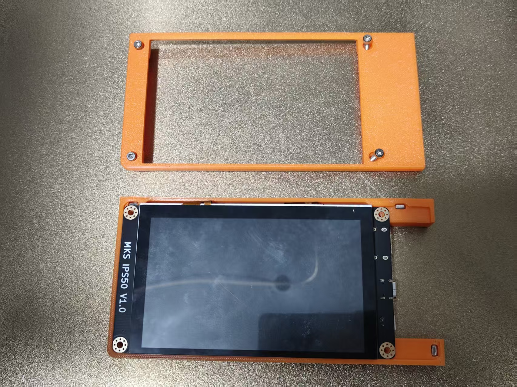
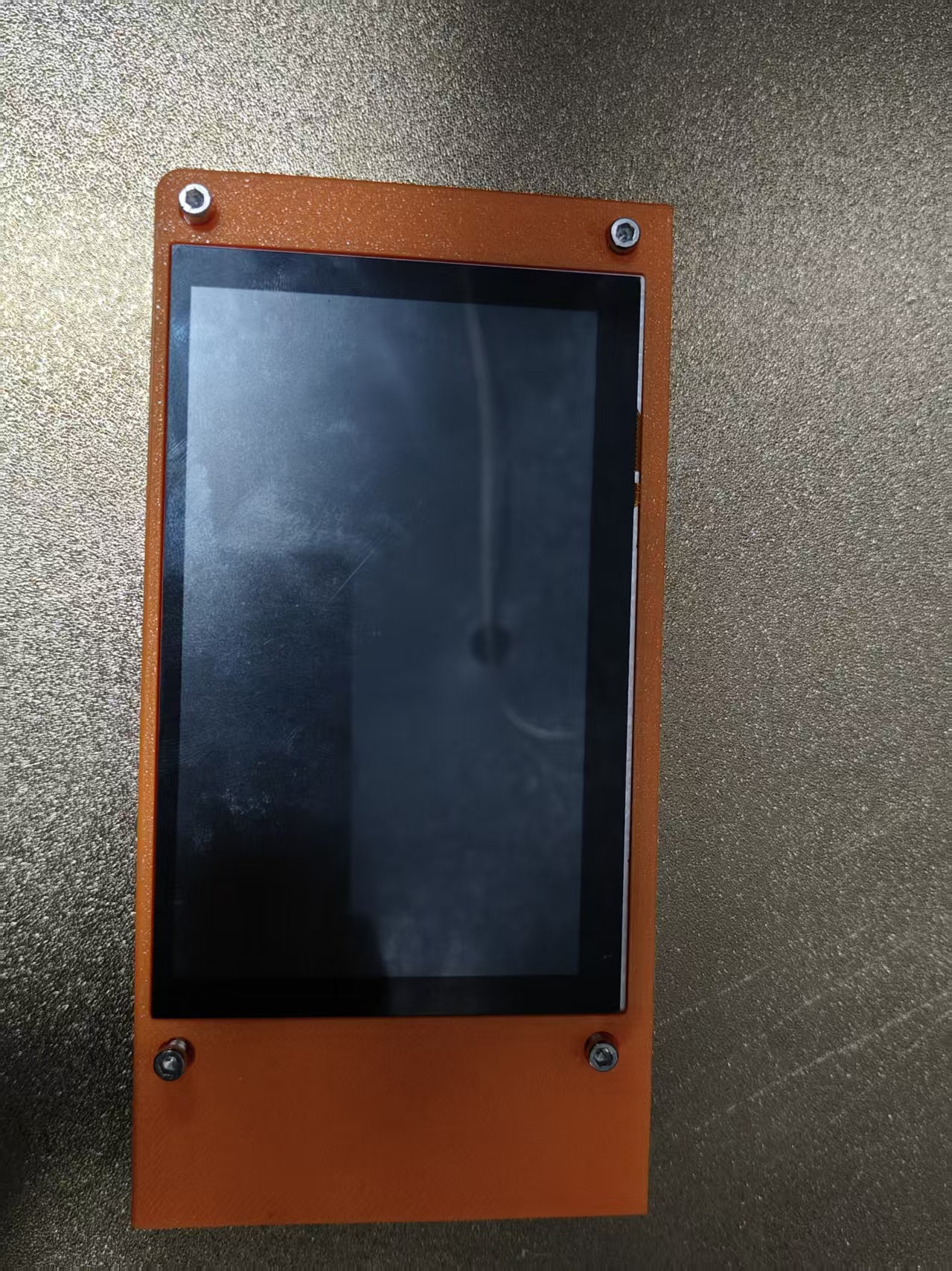
6.Tighten the 4 screws on the screen top cover.
7.Reconnect the 3 cables to the screen.
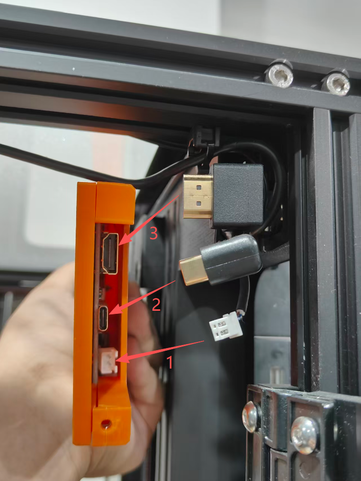
Suggestion: Insert the cables from bottom to top sequentially for easier installation
8.Secure the screen assembly back onto the Thinker X400 frame.
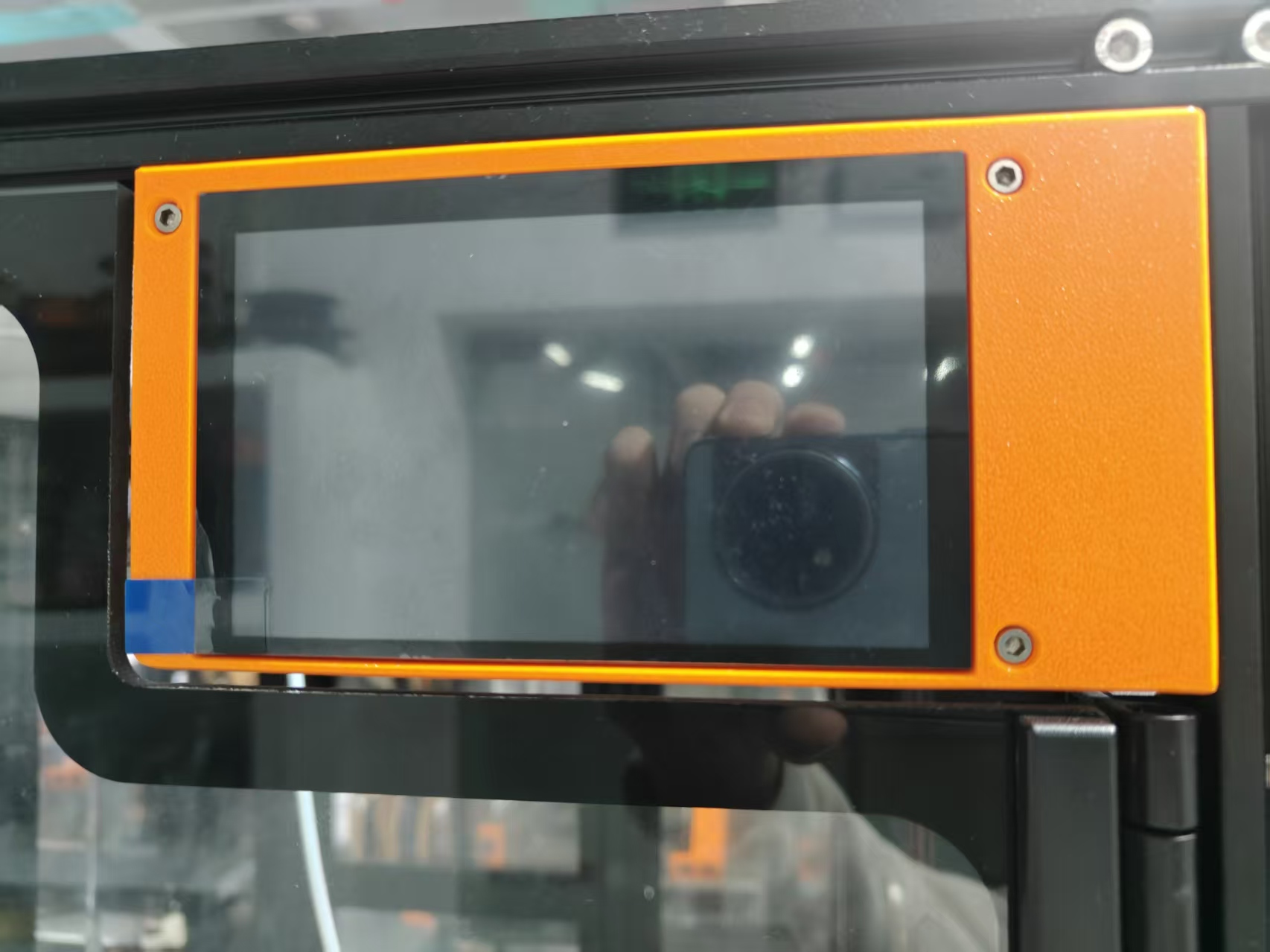
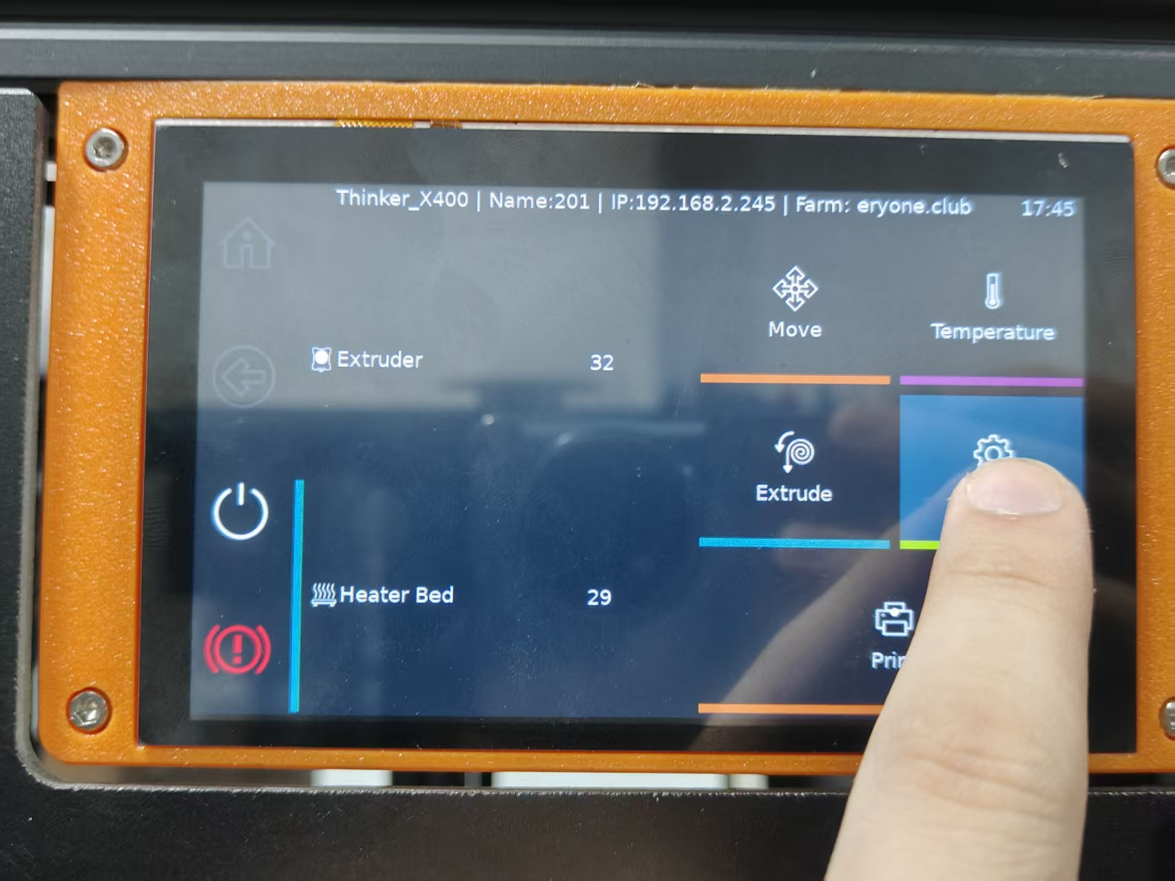
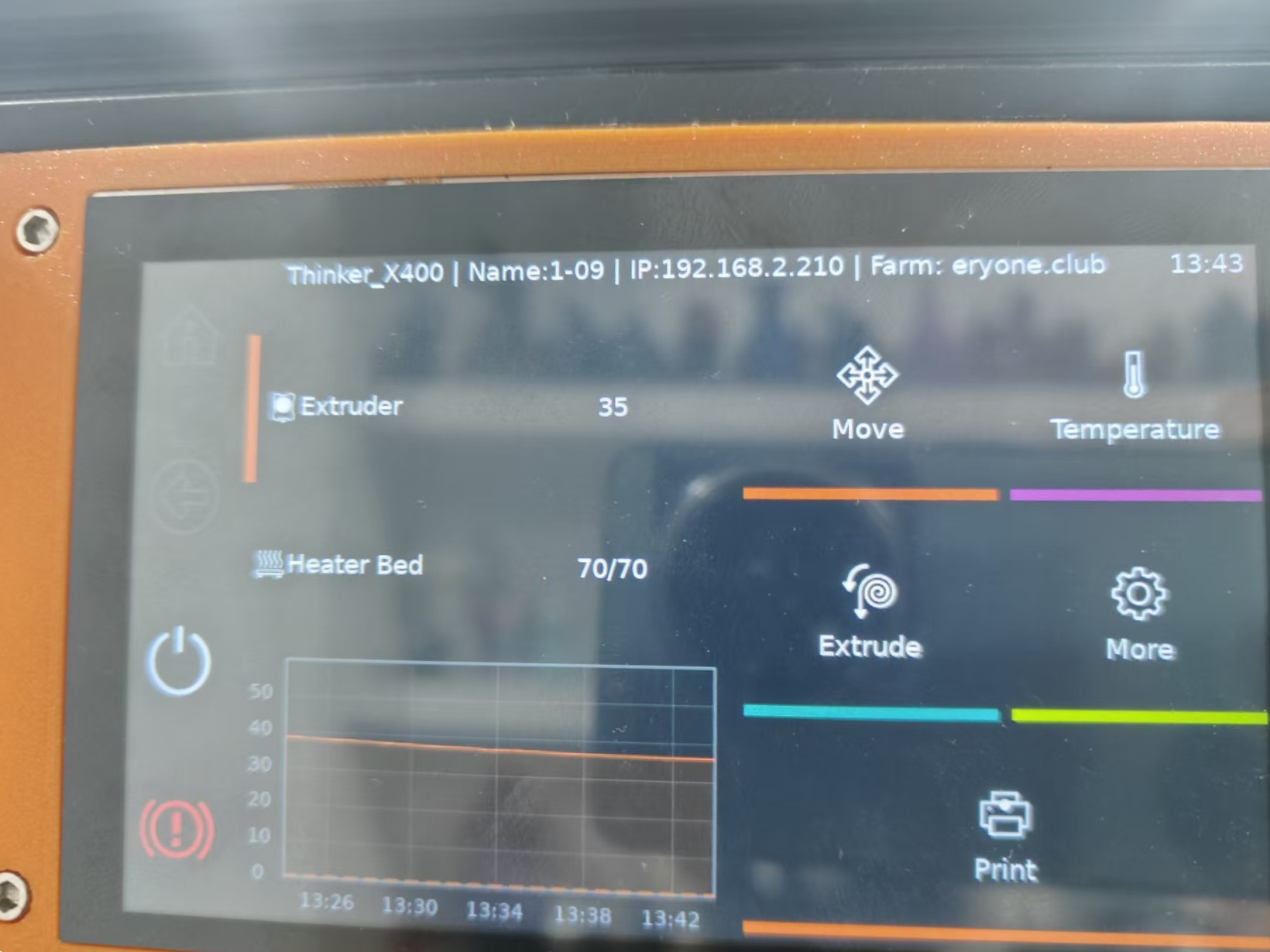
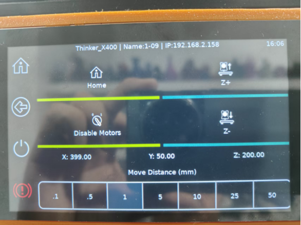
9.Start the Thinker X400 and check for a video output/image on the screen.
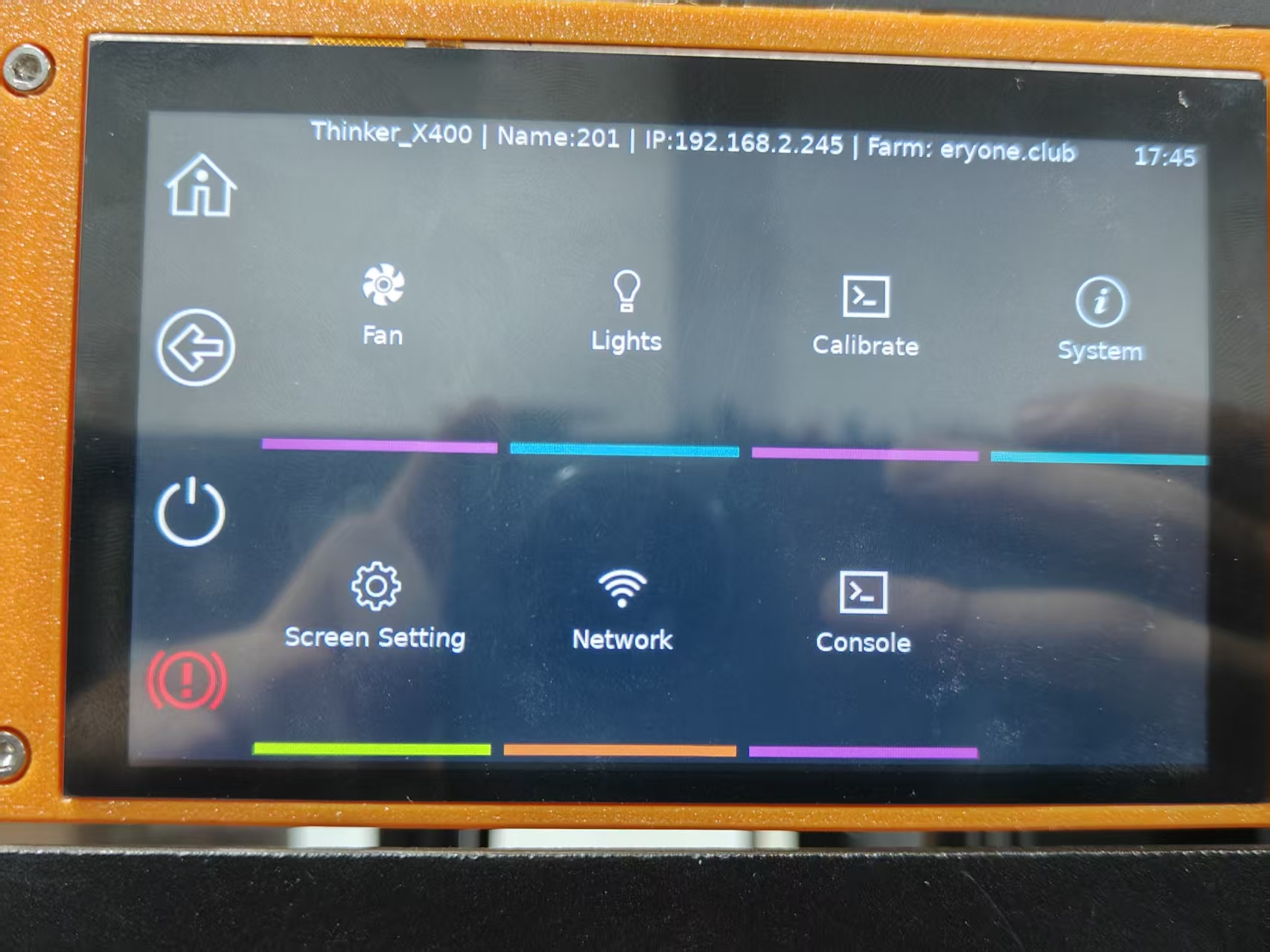
10.Once successfully booted to the main interface, verify screen functionality by tapping the on-screen buttons to ensure they respond correctly.
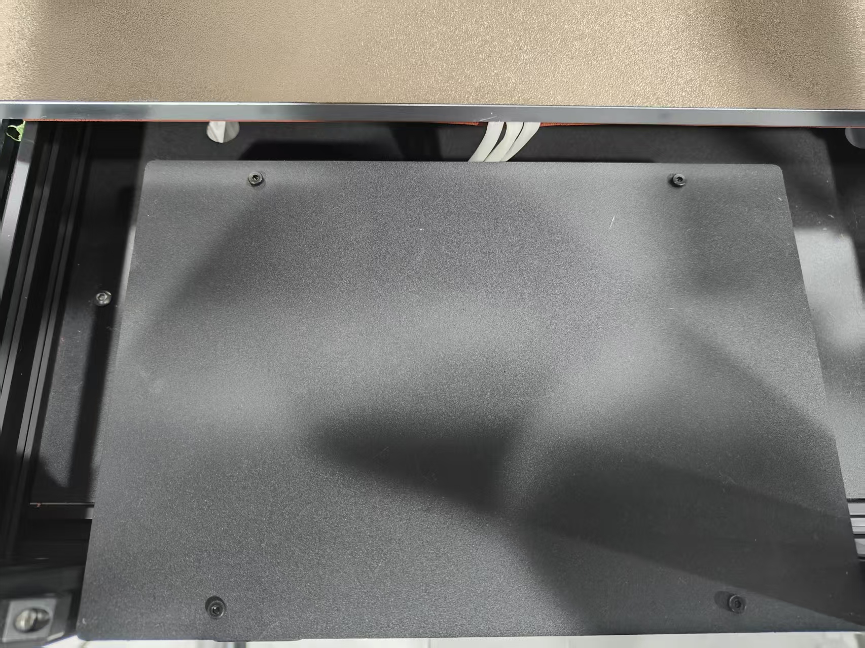
¶ Replace the Thinker X400 heated bed
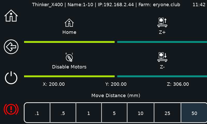
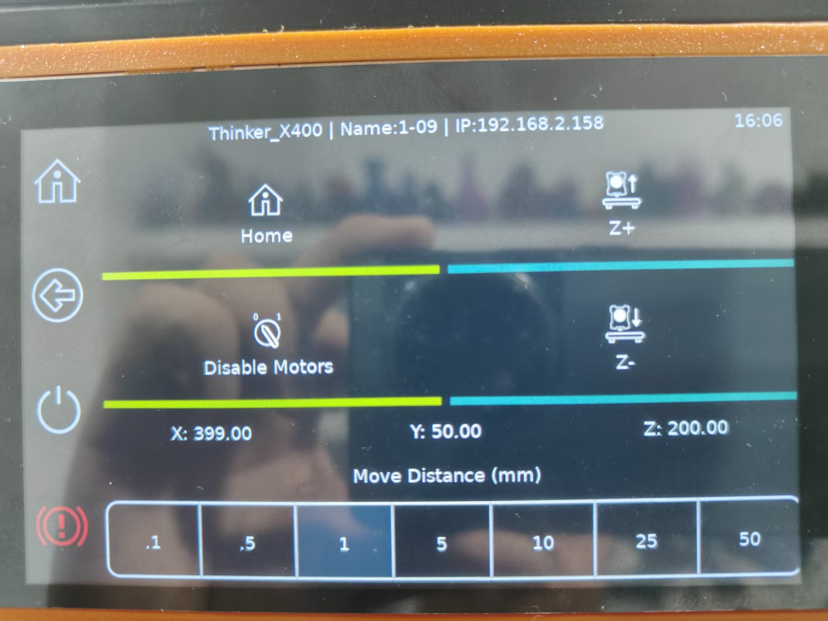
1.Lift the Z-axis by 200mm (for ease of operation)
2.Power off the Thinker X400 and disconnect it from the power source.
3.Remove the acrylic back panel and place it on top of the machine
Note: Handle with care to avoid damaging the fan cable.
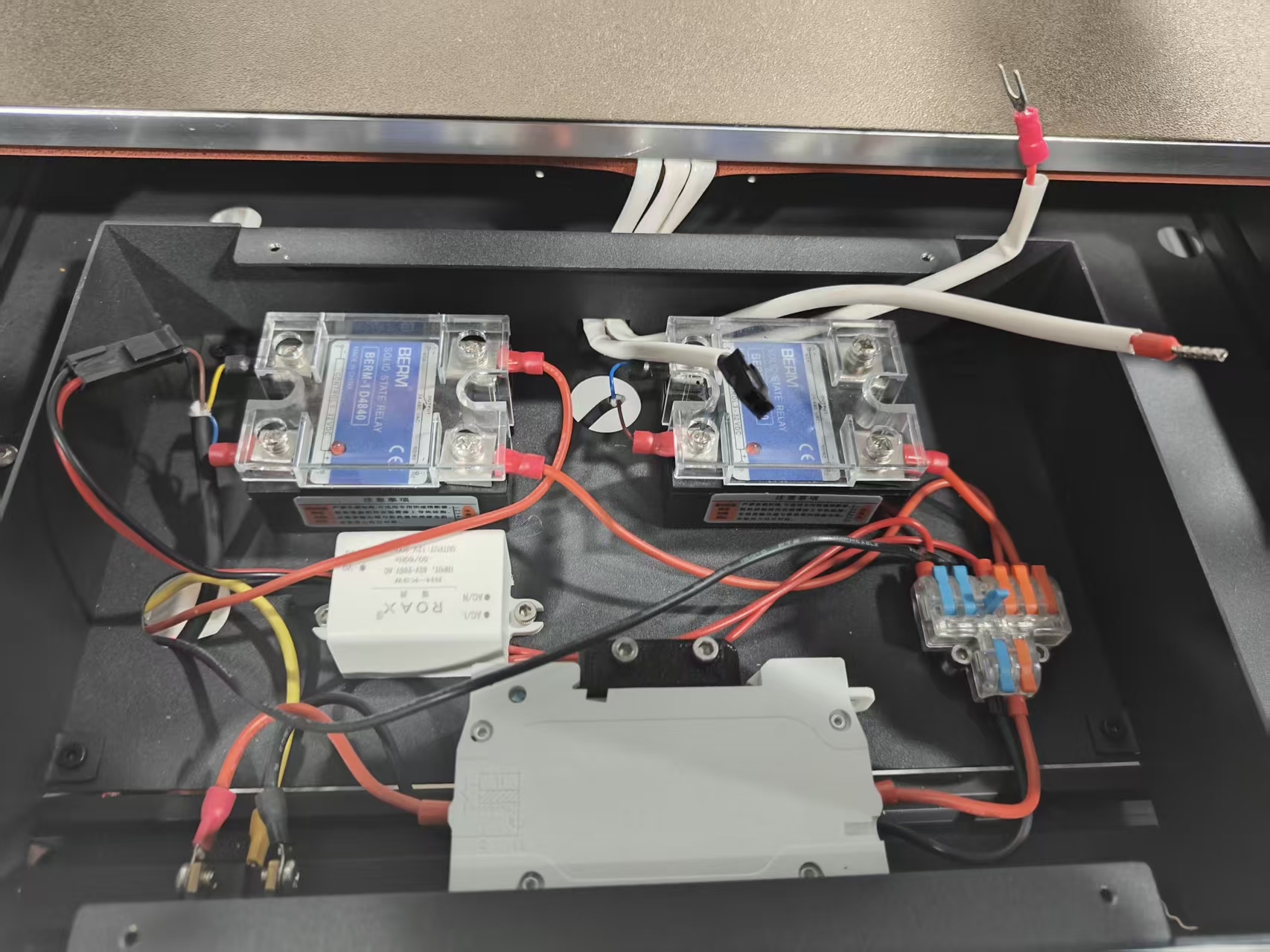
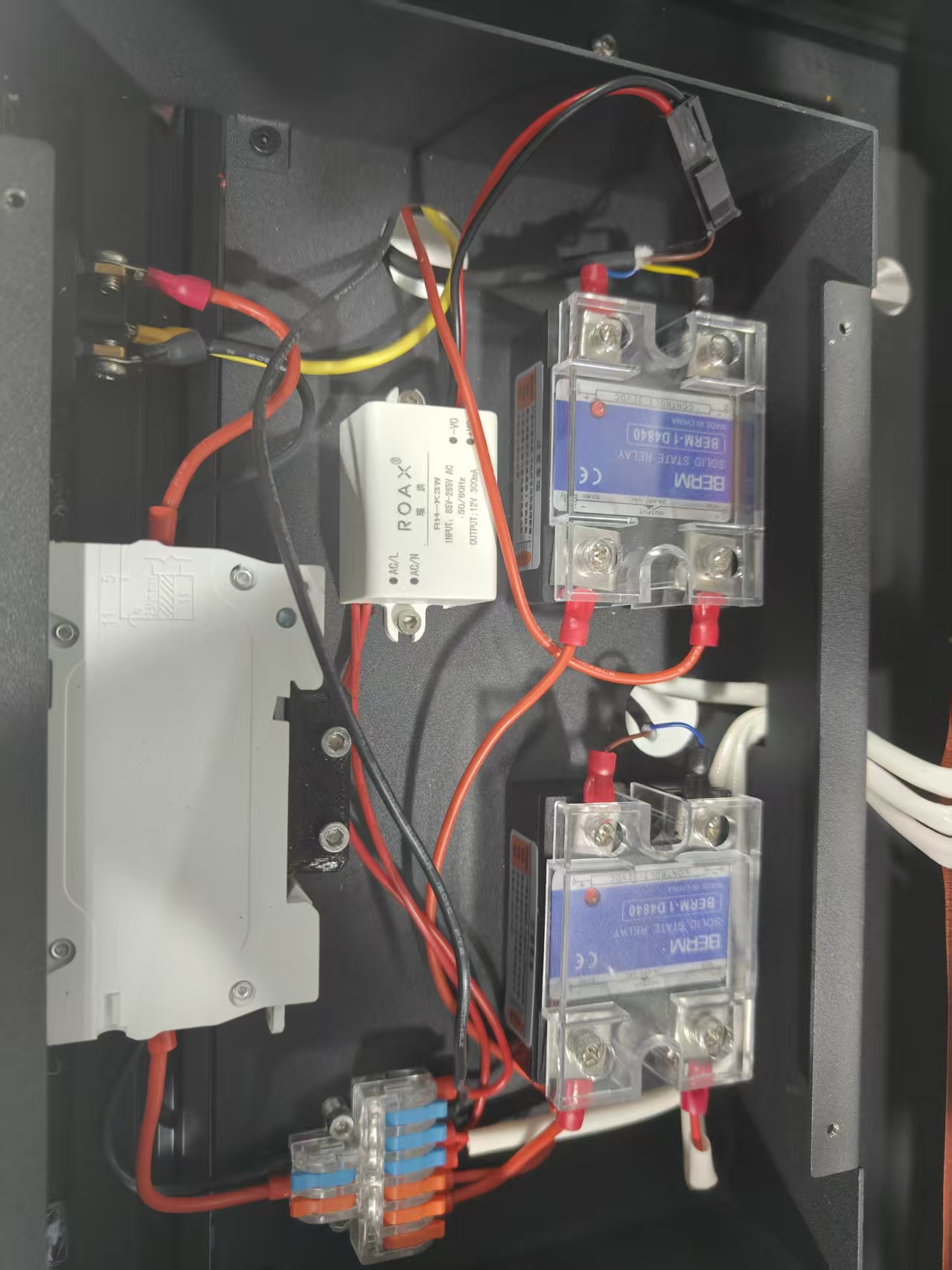
4.Remove the power supply cover.
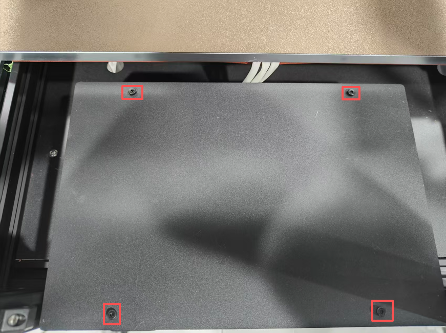
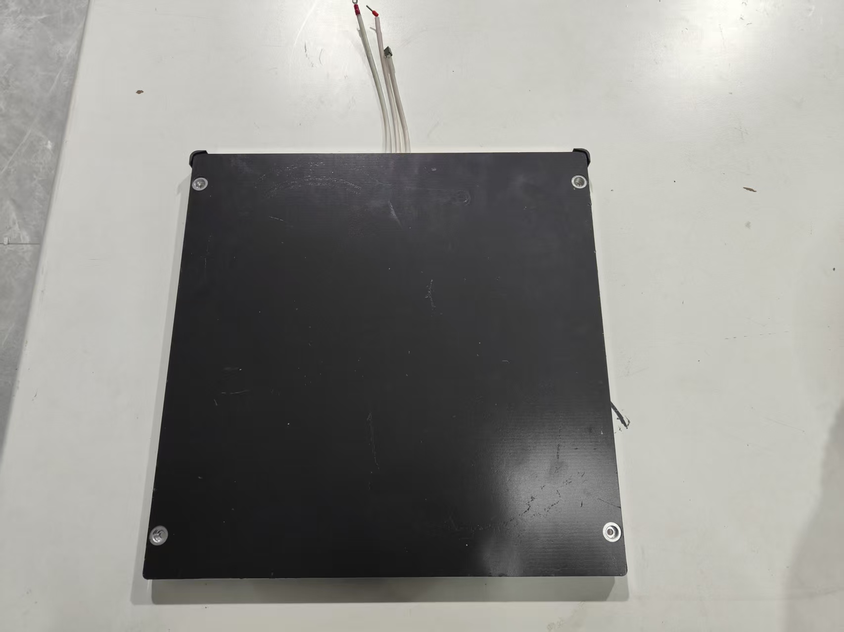
5.Disconnect the three white cables from the heated bed

6.Remove the four screws securing the heated bed
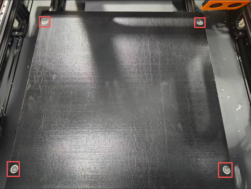
7.Remove the heated bed and set it aside
8.Remove the blocking plate that secures the PEI plate.
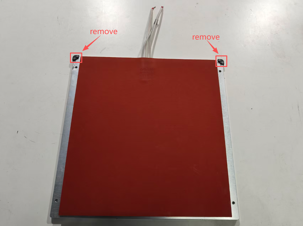
9.Take out the new heated bed and install the PEI plate baffle on the new heated bed
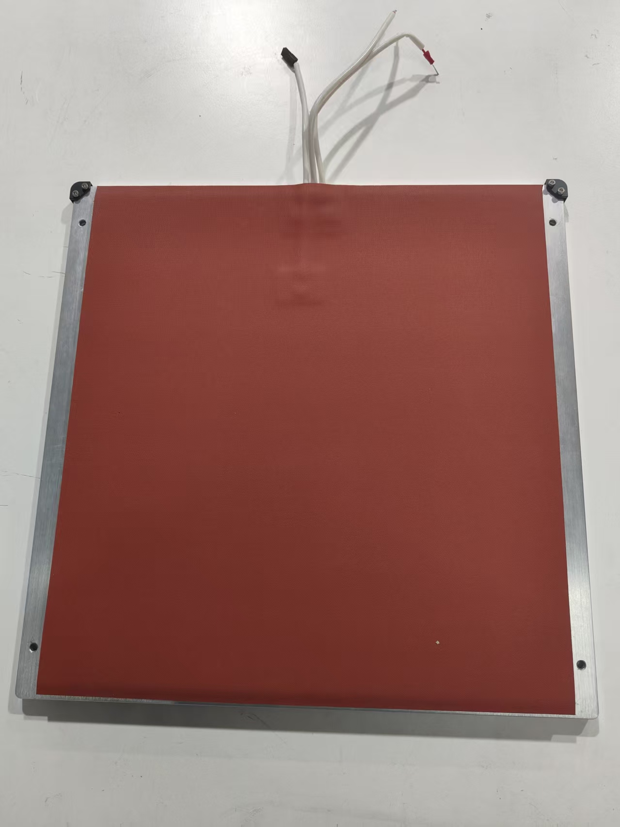
10.Route the heated bed cable through the power supply box opening and position the bed over the corresponding holes.
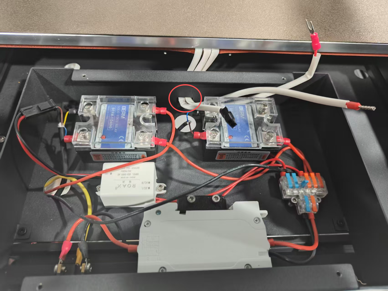
11.Reinsert the cable into its port
12.Reinstall and tighten the screws that secure the heated bed

13.Place the power supply cover back on and tighten the screws.
14.Reinstall the acrylic back panel
15.Reconnect the power cable to the Thinker X400 and power it on
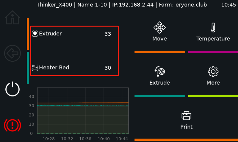
16.Once the main interface is successfully loaded, perform a standalone heated bed test. If it heats up without any issues, the machine is ready for normal use
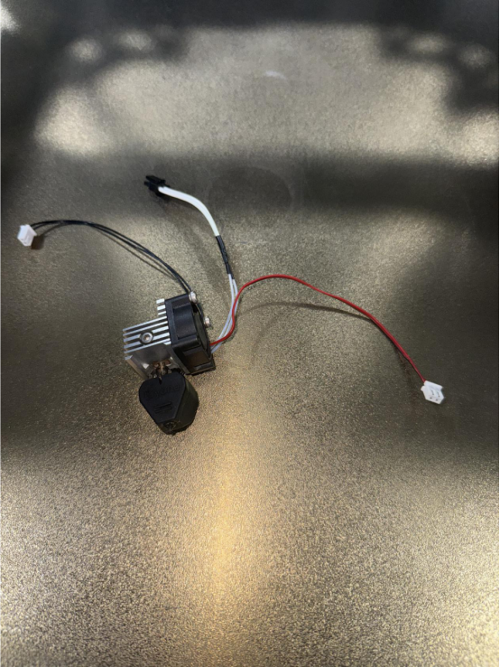
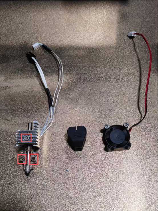
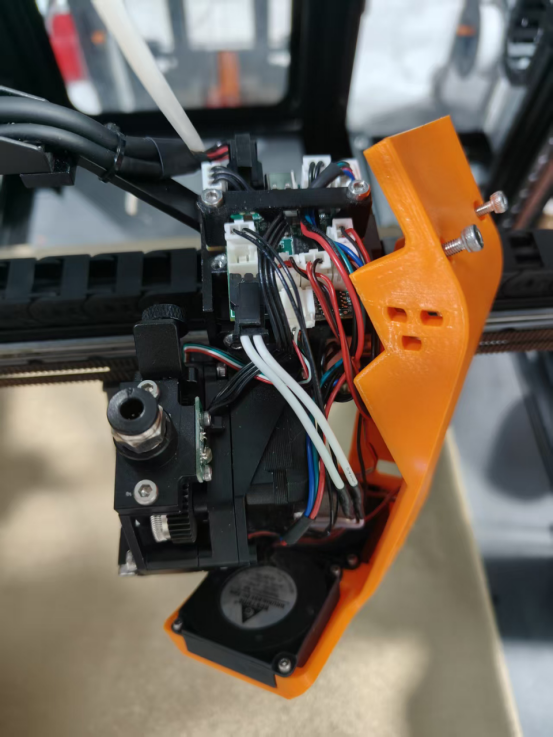
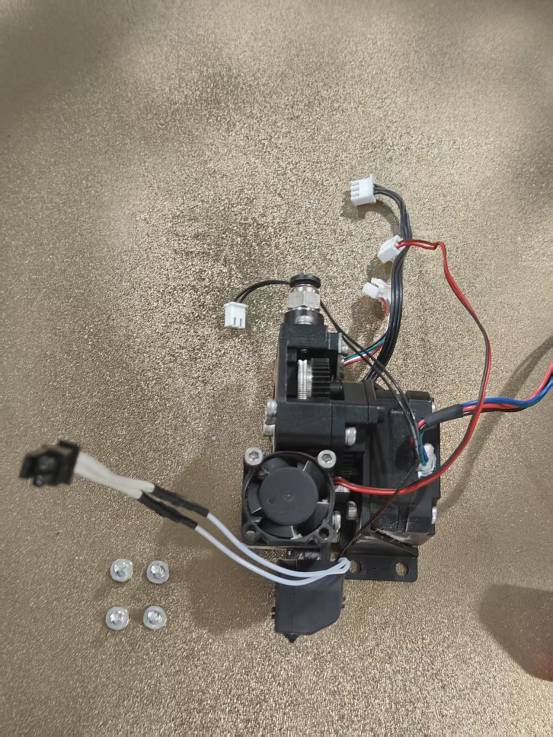
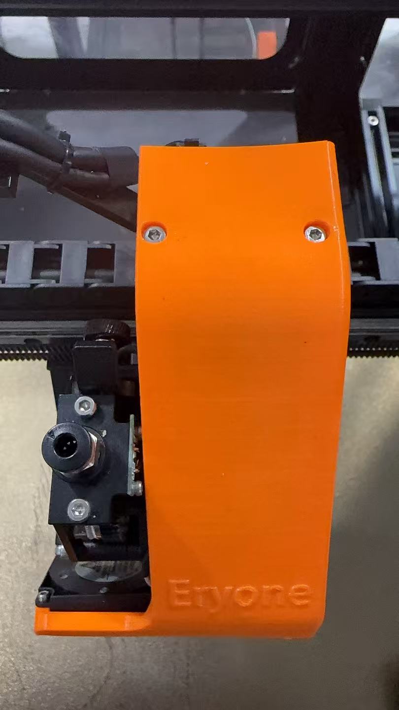
¶ Replacing the hot end assembly
Installation steps:
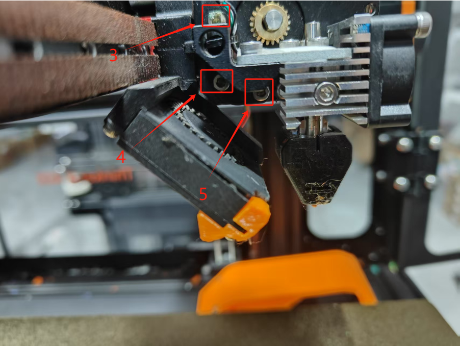
1.Remove the extruder support cover and fan cable terminal.

2.Remove the extruder wheel module and the filament runout sensor cable.
3.Remove the three screws securing the heat sink
4.Disconnect the cables from the hot end.
5.Remove the silicone sleeve.
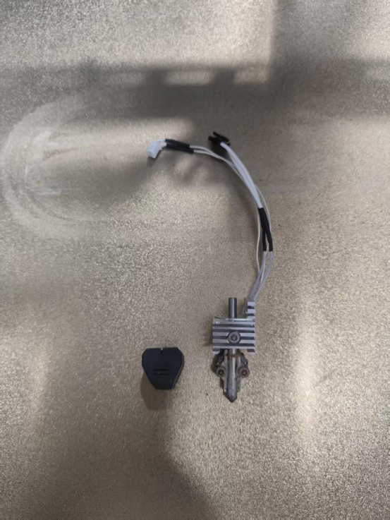
6.Remove the heatsink fan.
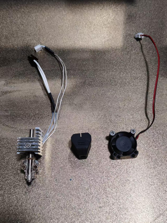
7.Remove the nozzle.
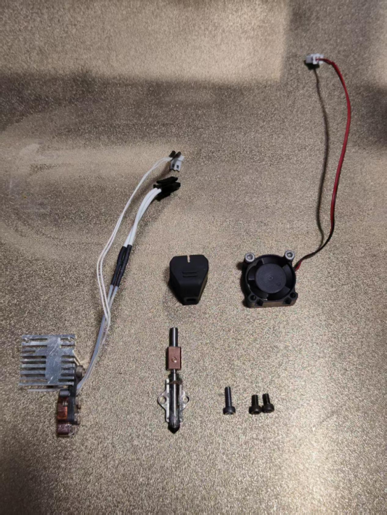
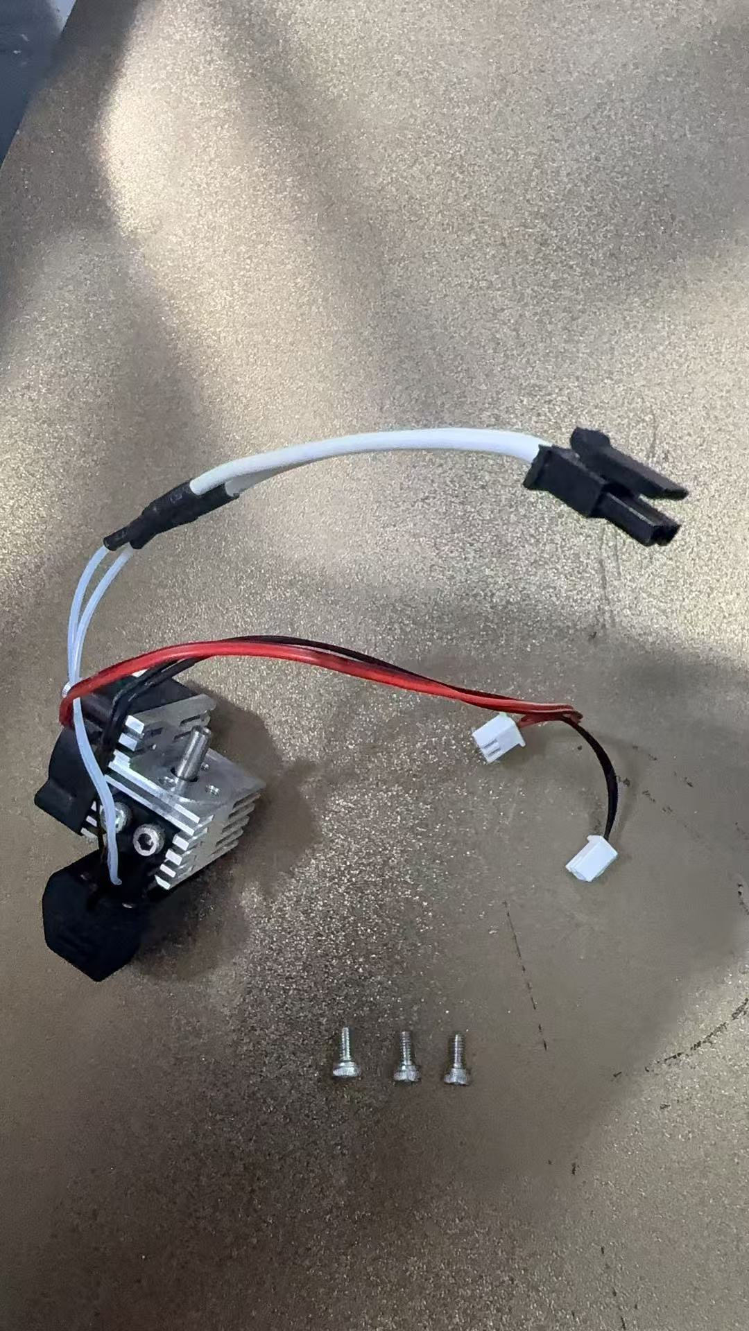
8.Take out the new extruder heating module.
9.Install the nozzle.

10.Install the heatsink fan.
11.Install the silicone sleeve.
12.Reinstall the entire hot end assembly.
13.Plug the hot end cables back into the Canbus board.
14.Reinstall the extruder wheel module and plug the cables back in.
15.Reinstall the extruder bracket cover.
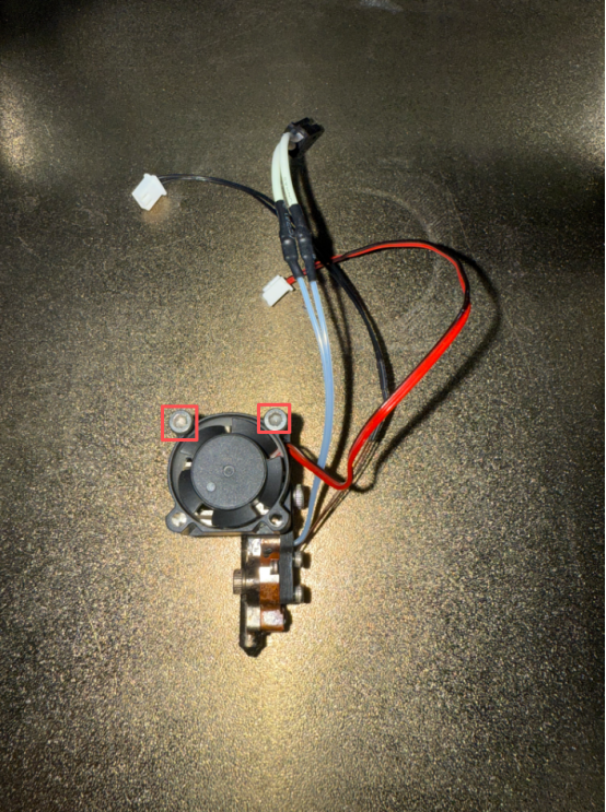
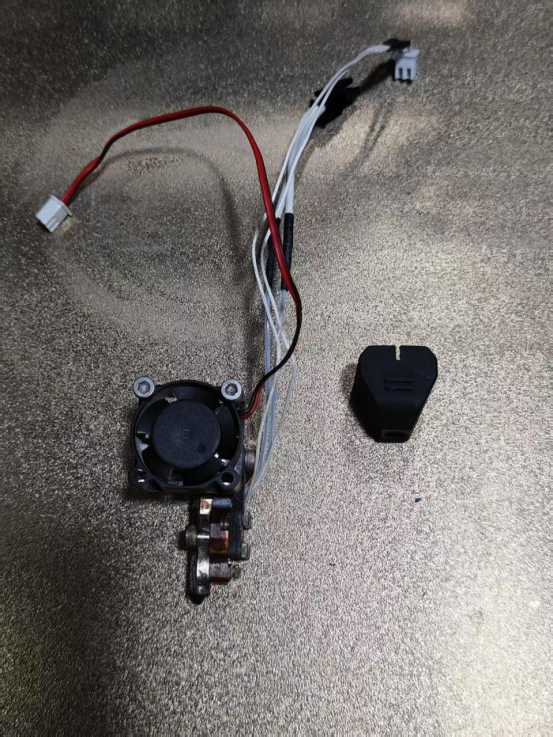
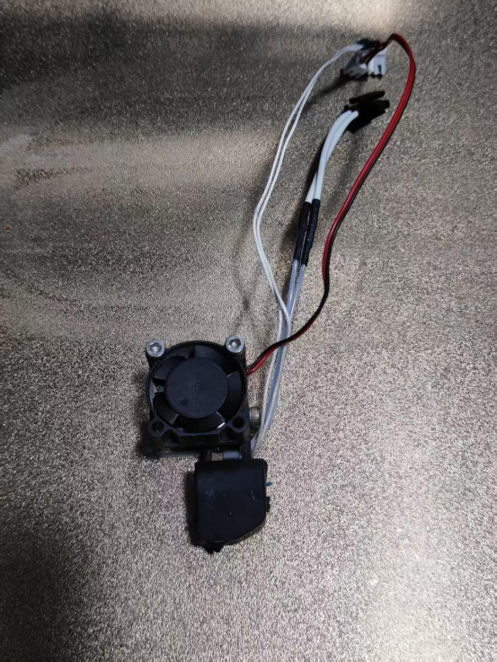
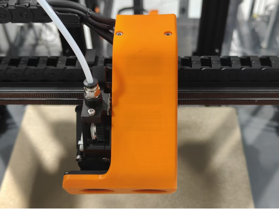
¶ Replacing the hot end cooling fan
Video tutorial:
1.Raise the CoreXY frame up by 200mm.

2.Turn off the power.

3.Remove the rear acrylic panel and place it on top of the machine.
Caution: Do not pull or disconnect the wires.
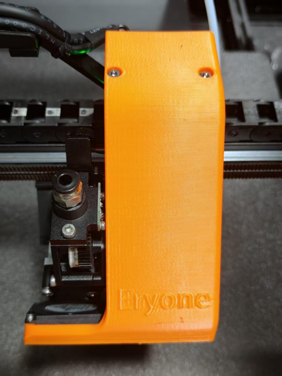
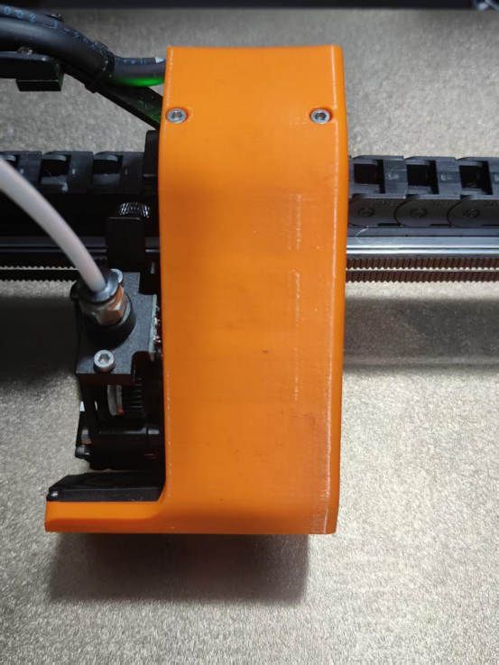
4.Remove the extruder bracket cover.


5.Unplug the model cooling fan cable.
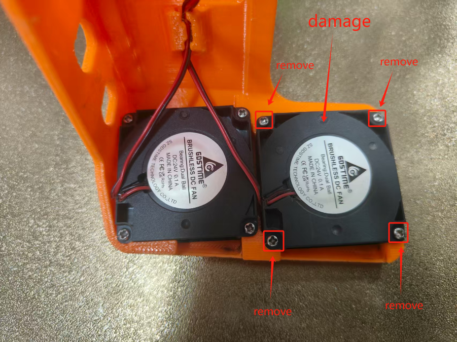
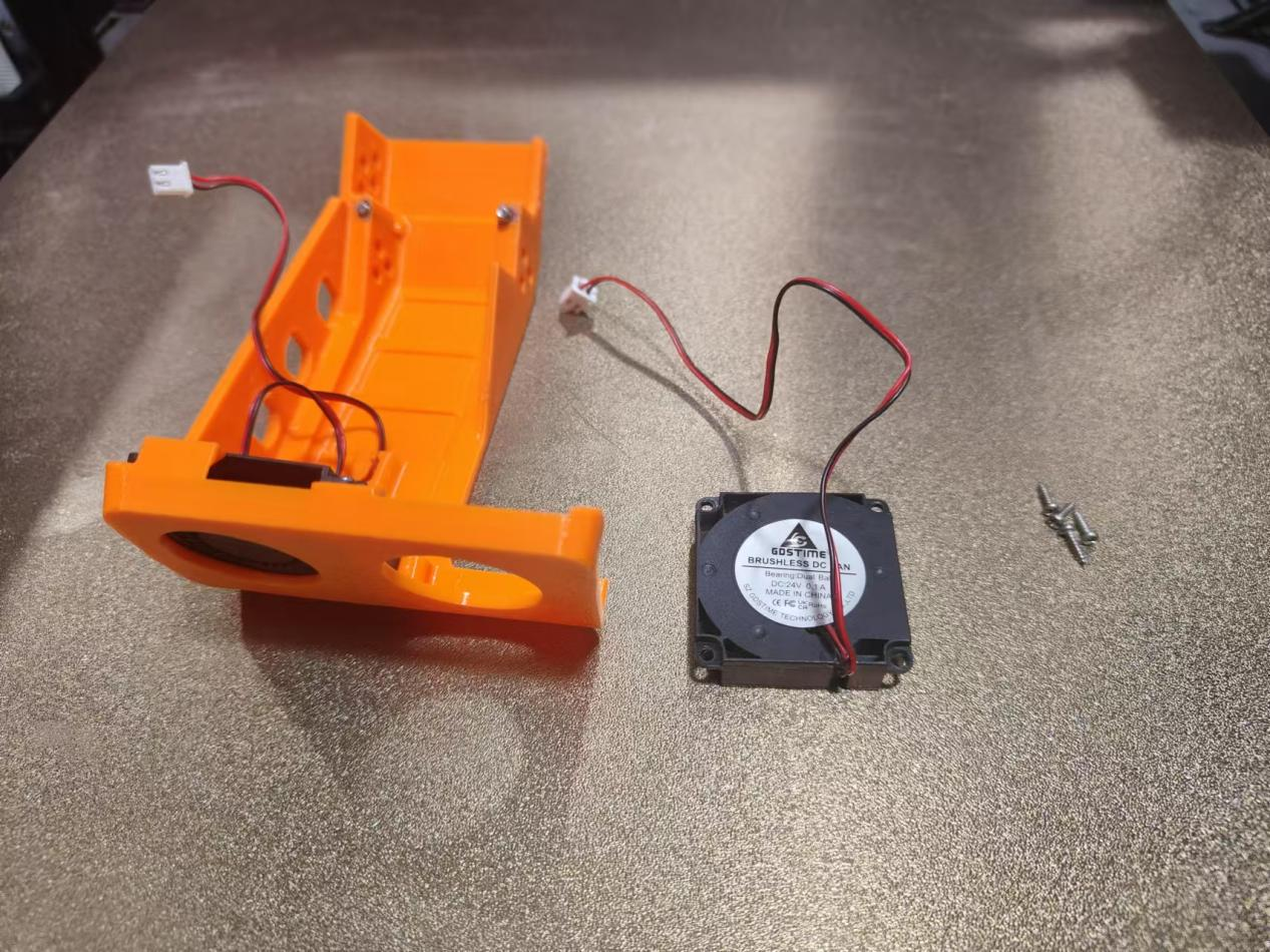
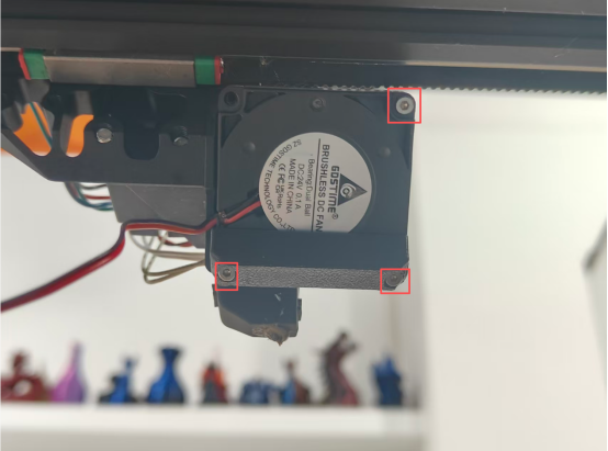
6.Remove the model cooling fan.
7.Detach the air duct nozzle from the damaged model cooling fan.
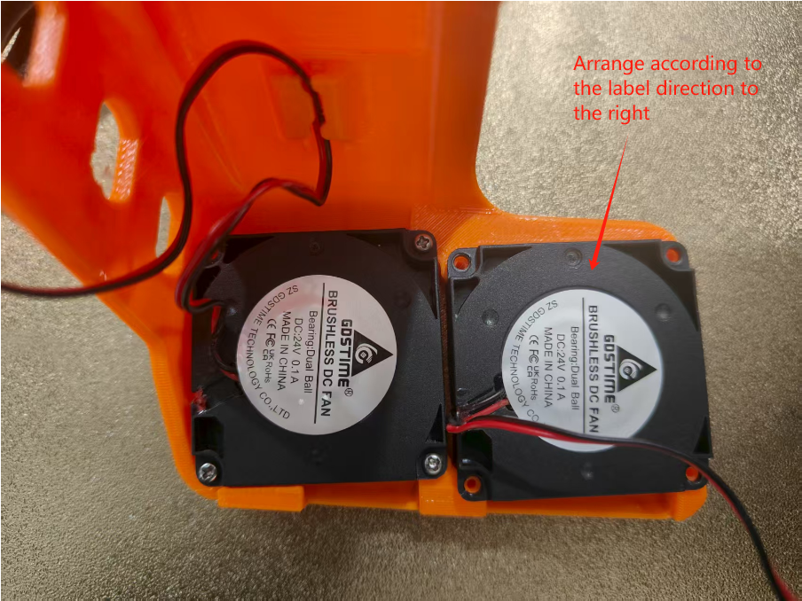
8.Install the air duct nozzle onto the new model cooling fan.
9.Install the model cooling fan onto the Thinker X400.
10.Plug the wire terminal back into the Canbus adapter board.
11.Reinstall the fan and extruder bracket cover.
12.Power on the Thinker X400.

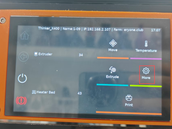
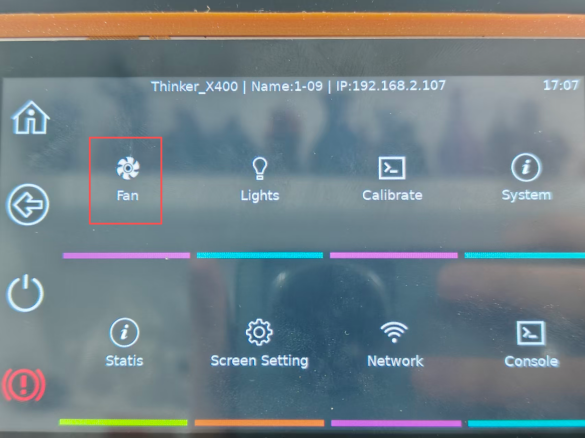
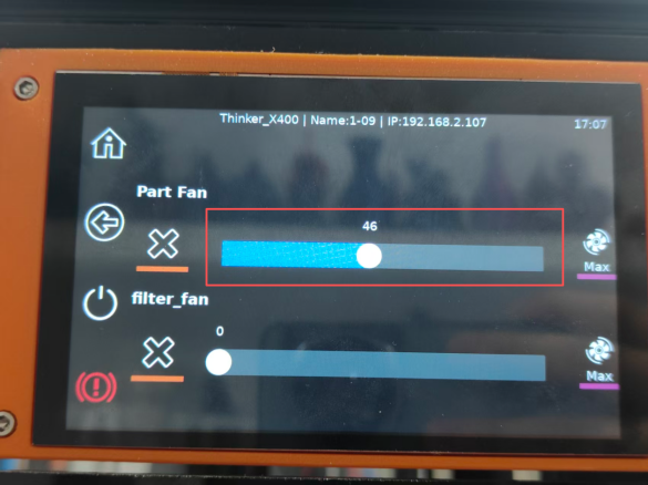
13.Open the fan control interface to check if it is functioning.
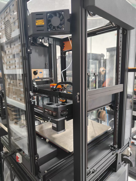
¶ Replace the CoreXY belt
1.Raise the Z-axis by 200mm.

2.Turn off the power.
3.Remove the acrylic panels on the left and right sides, as well as the left and right corner acrylic panels.
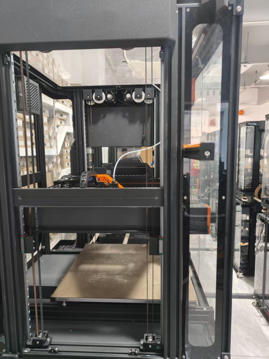
4.Remove the rear acrylic panel and flip it upward for placement
Note: Avoid pulling or damaging the fan cables

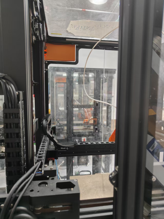
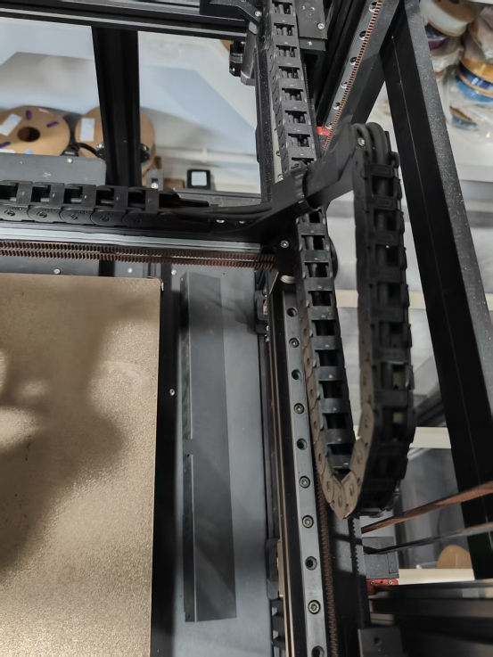
5.Remove the 2 screws securing the Y-axis cable chain (tank track).
6.Remove the X-axis cable chain (tank track) bracket.
7.Remove the left and right covers of the CoreXY assembly.
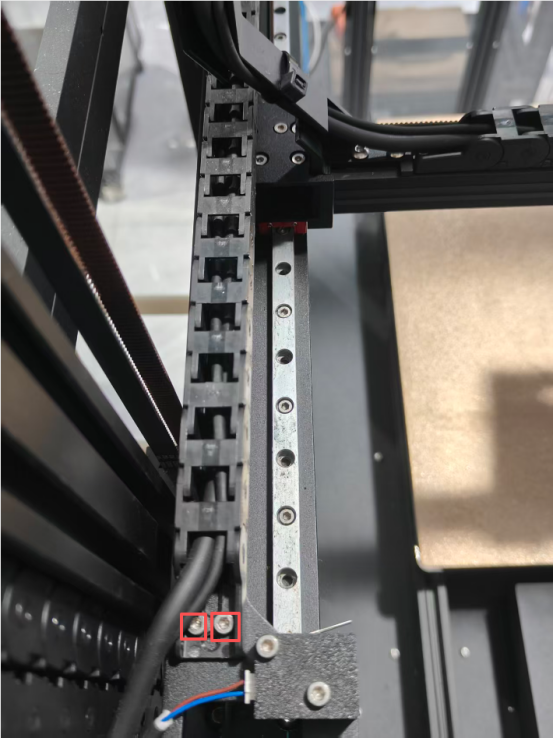
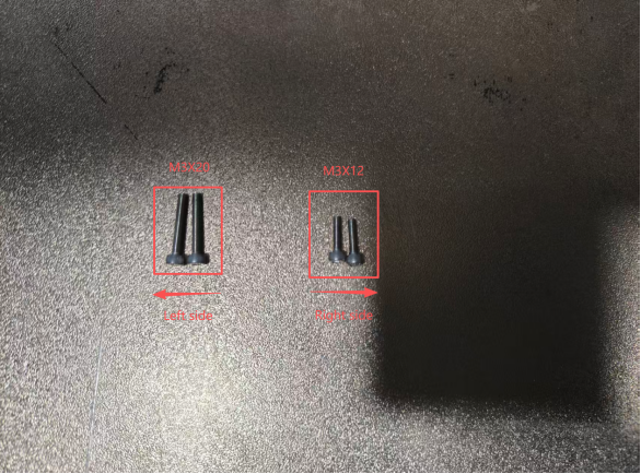
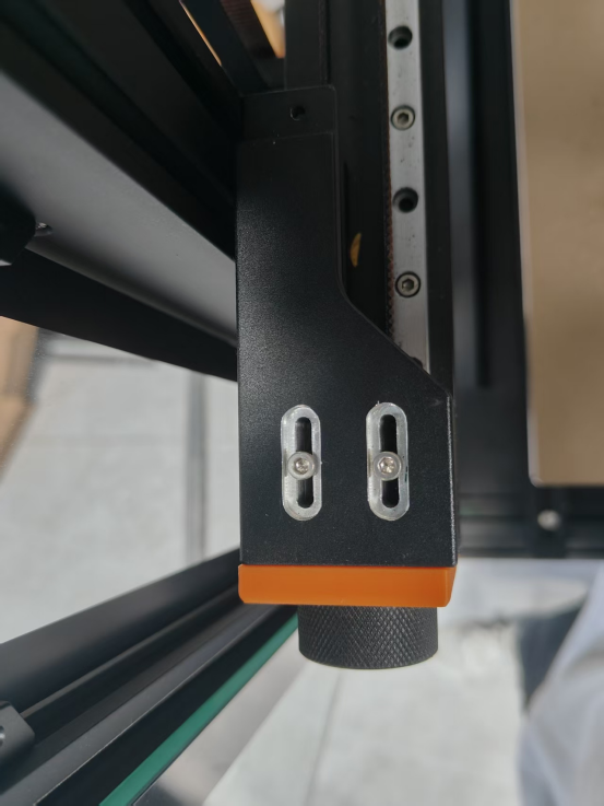
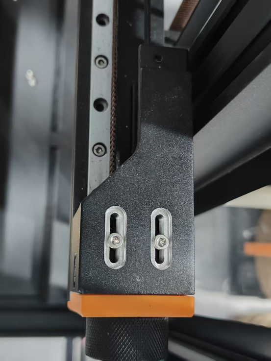
8.Remove the 4 screws securing the CoreXY belts on both sides (Left side: M3x20; Right side: M3x12).
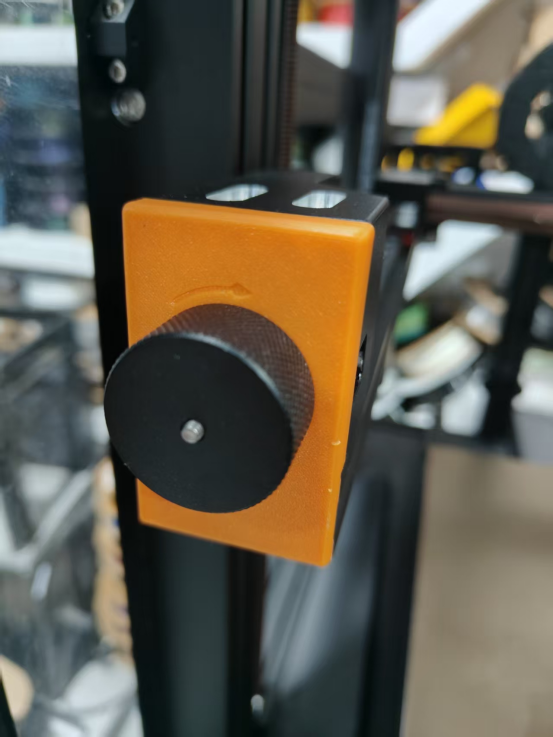
9.Remove the black knobs and springs on both sides, then pull out the idler wheel frame.
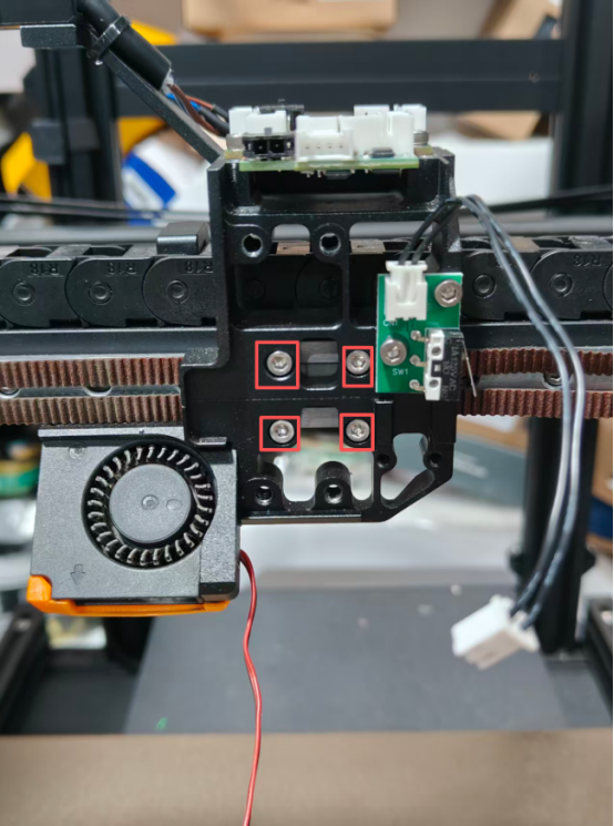
10.Remove the extruder mounting bracket cover.
11.Disconnect the cable ends from the CAN Bus board.
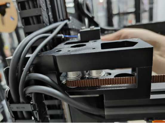
12.Remove the entire extruder assembly.
13.Remove the print head mounting bracket and pull out the belt.
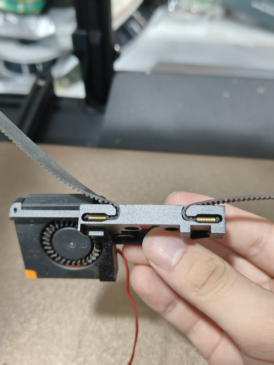
14.Remove the cover securing the idler wheel frame, then take out the idler wheels, pins, and belt.
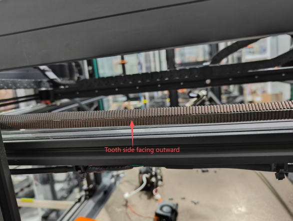
15.Take a new belt, and thread one end of the belt through the left and right pulleys
(toothed side facing outward) (The left strap runs under the right strap.).
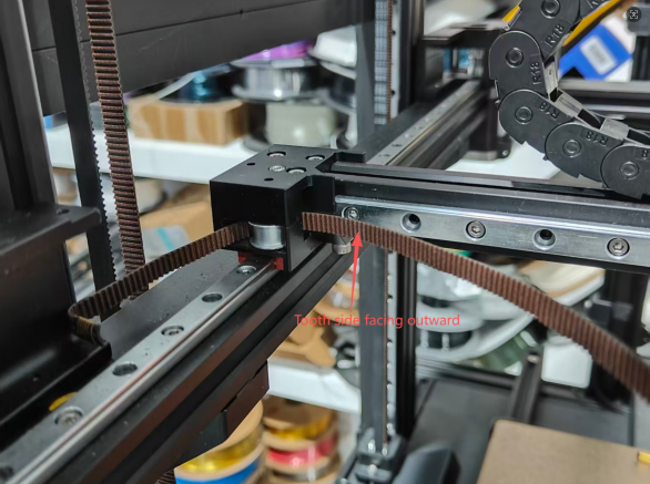
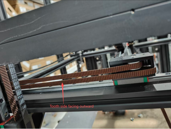
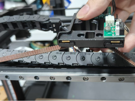
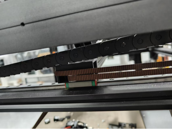
16.Thread the belt through the X and Y motor mounts (toothed side facing outward).
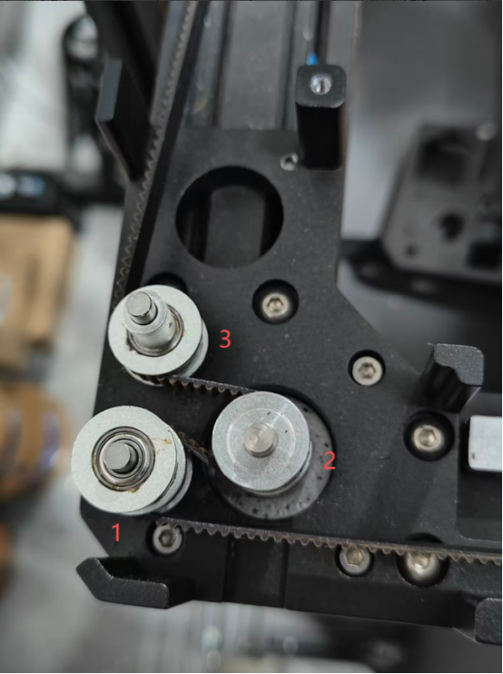
17.Thread the belt through the left/right pulleys on the other side.

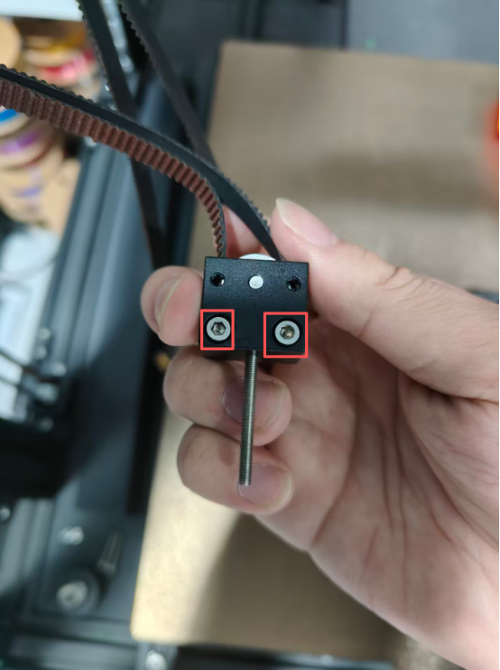
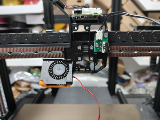
18.Secure the belt into the print head mounting bracket and tighten the screws to fix it onto the slider.
19.Place the idler wheels, pins, and belt into the idler wheel base frame, then close the outer cover and tighten the screws.
20.Insert the assembled idler wheel frame into the small holes on the front of the CoreXY frame, then reinstall the black knobs and springs. Adjust the belt tension.
21.After adjusting the belt tension, tighten the screws (Left side: M3x20; Right side: M3x12).
22.Reinstall the left and right covers of the CoreXY assembly.
23.Secure the Y-axis cable chain and the X-axis cable chain bracket.
24.Reinstall the entire extruder assembly.
25.Reconnect the cables to the CAN Bus board.
26.Install the extruder mounting bracket cover.
27.Install the acrylic panels.
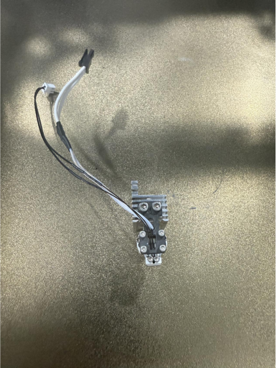
¶ Replace the weighting senior
Video tutorials:
1.Remove the Teflon tube
2.Remove the extruder support cover
3.Disconnect the corresponding wire.
3.Remove the extrusion wheel module
4.Remove the hot end
5.Remove the weighting
6.Install the new weighting senior and connect it to the corresponding port.
7.Install the hot end and connect the wiring to the corresponding port.
8.Install the extrusion wheel module and connect the wiring to the port.
9.Connect the fan to the extrusion wheel bracket cover and secure the extrusion wheel bracket cover.
10.Connect to Teflon tube
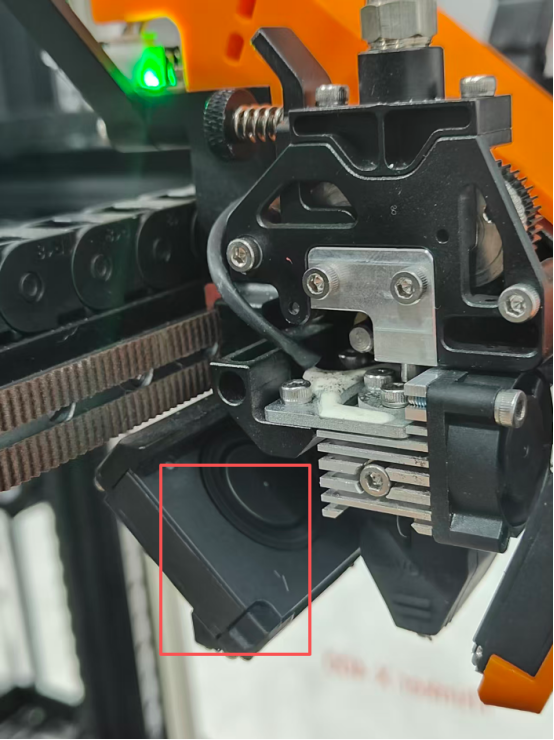
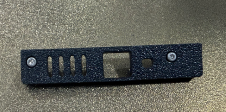
¶ Replace camera components
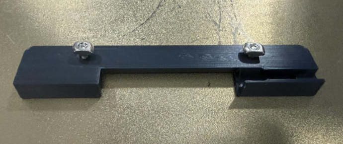
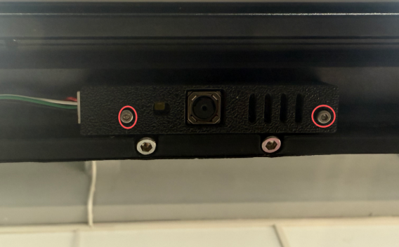
¶ Replace camera board
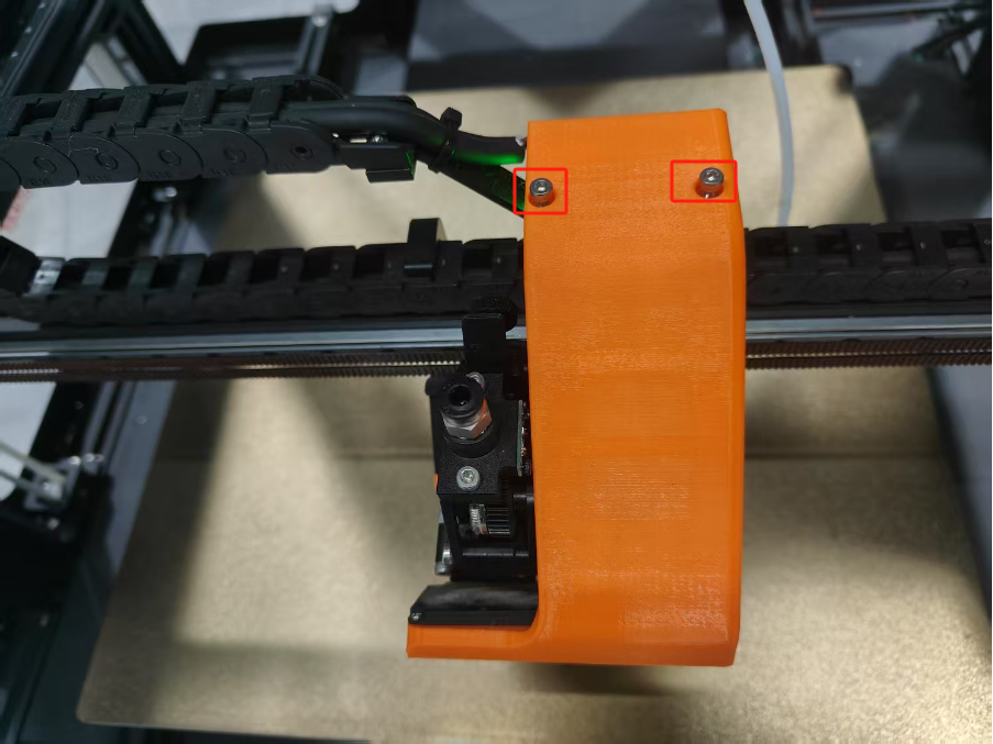
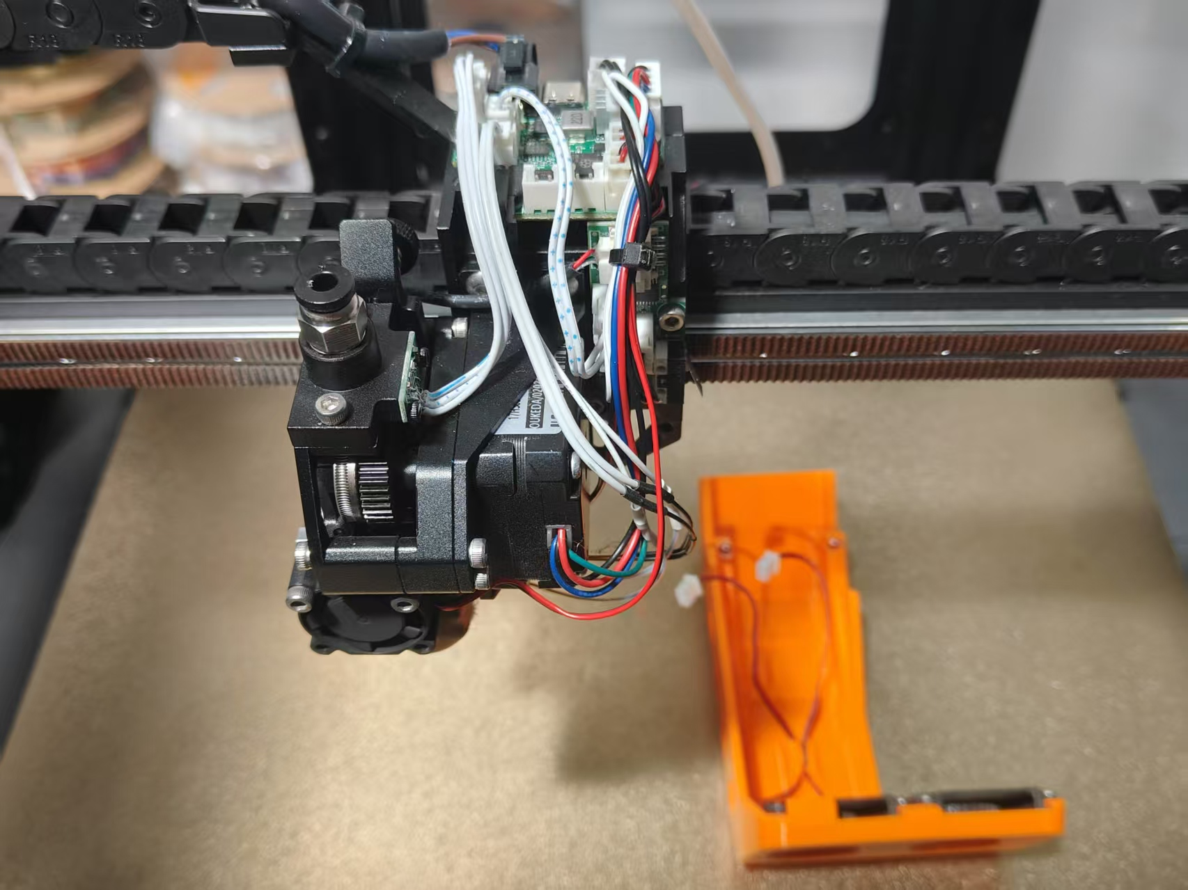
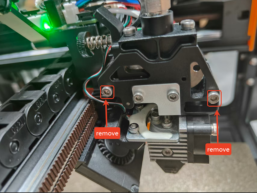
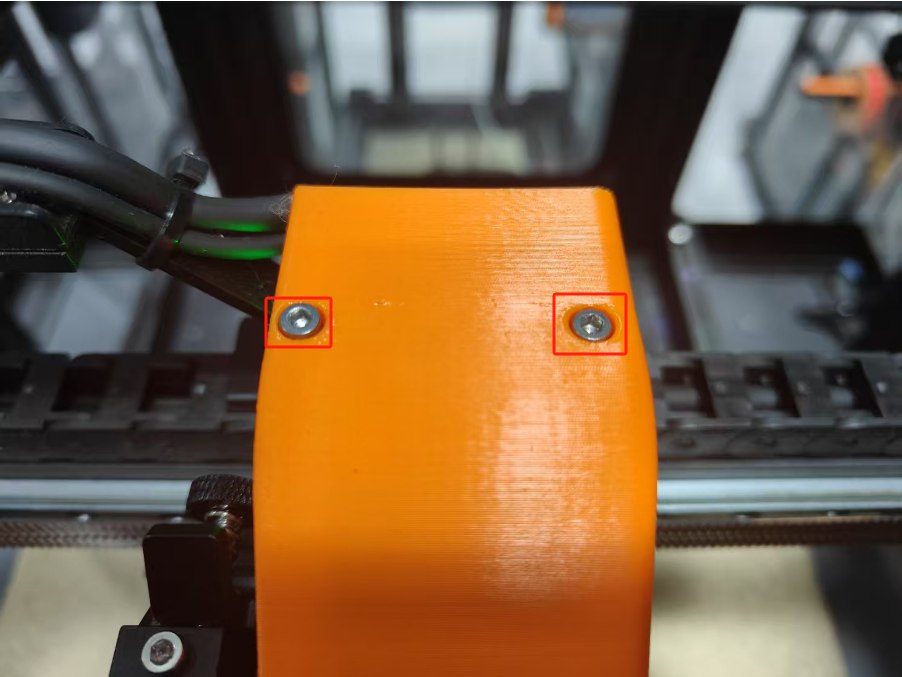
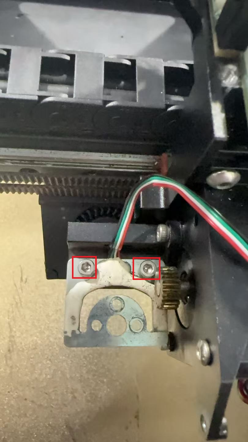
1.Remove the two large screws on the left and right sides.
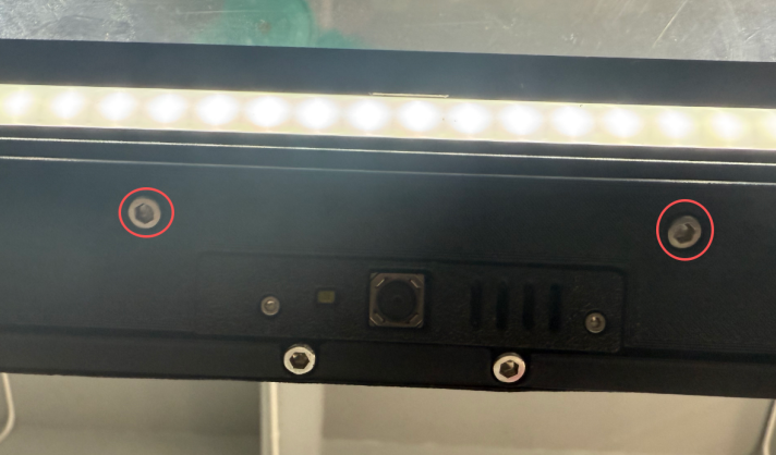
2.Remove the two small screws in the middle.
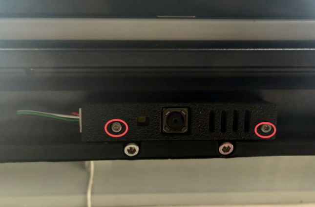
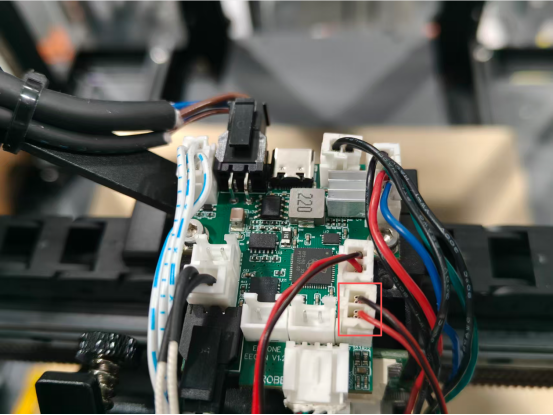
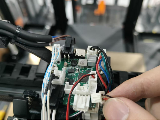
3.Disconnect the wiring from the camera circuit board.
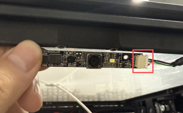
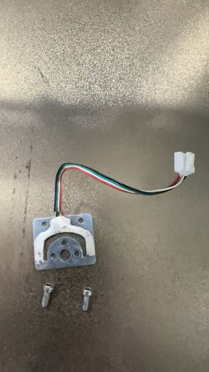
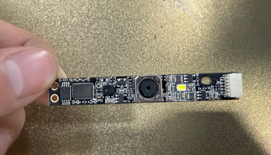
4.Take out the new camera board
5.Connect the wiring and tighten the small screws again.
6.Re-tighten the large screws on the left and right sides
¶ Replace camera wiring
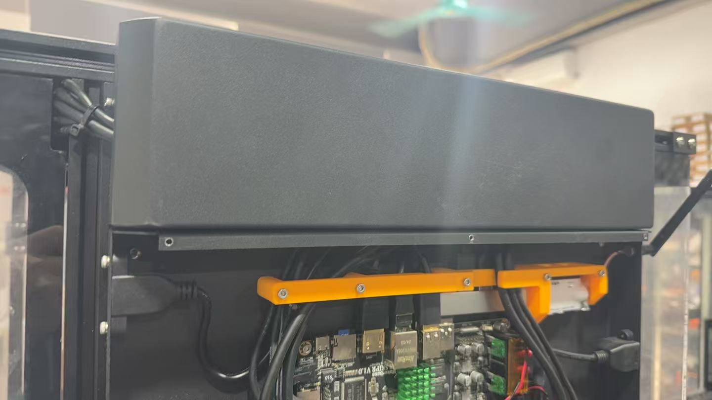
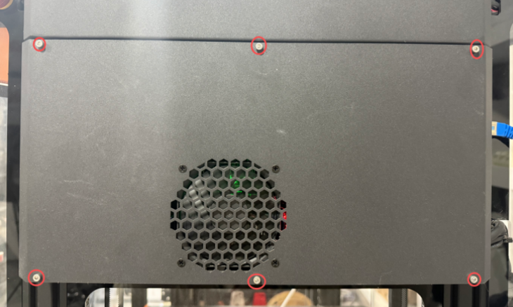
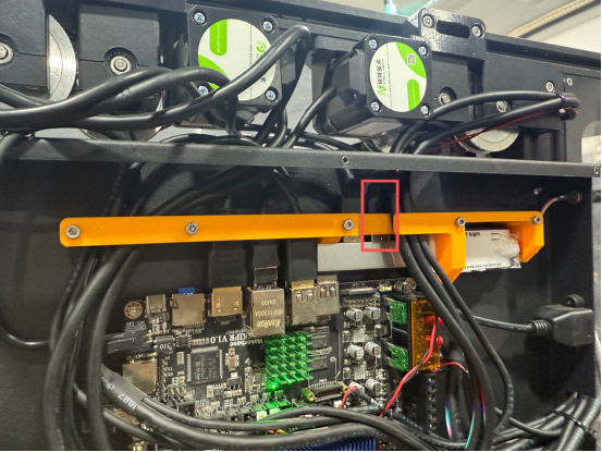
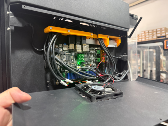
1.Remove the six screws from the motherboard.
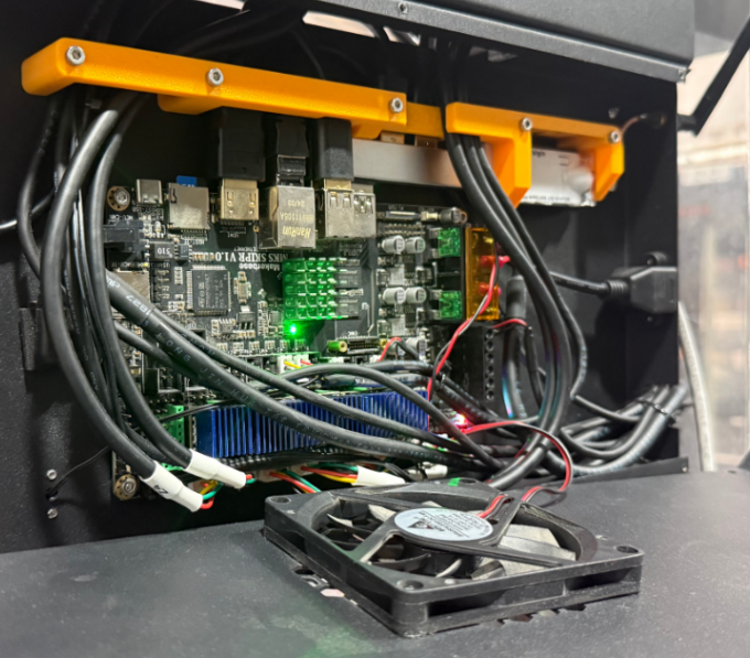
2.Disconnect the motherboard fan cable
3.Unscrew the left and right fixing screws on the top cover and remove the outer cover of the Z motor.
4.Remove the right front acrylic panel
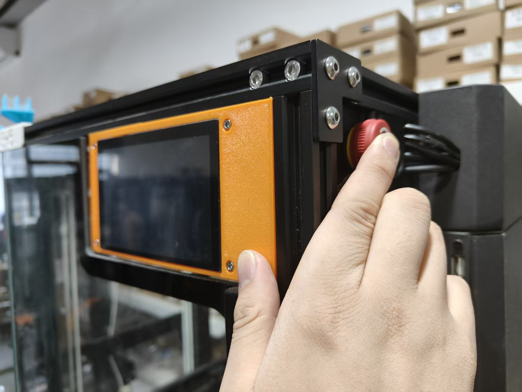
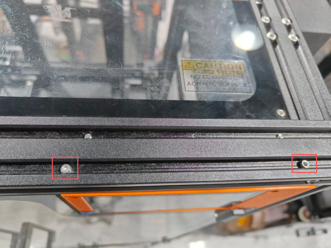
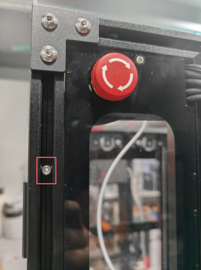
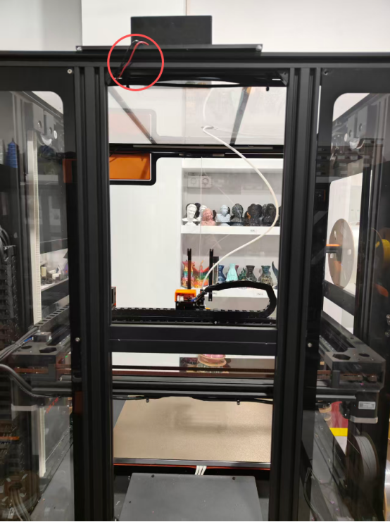
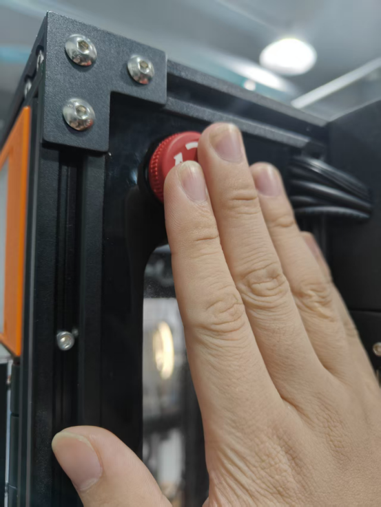
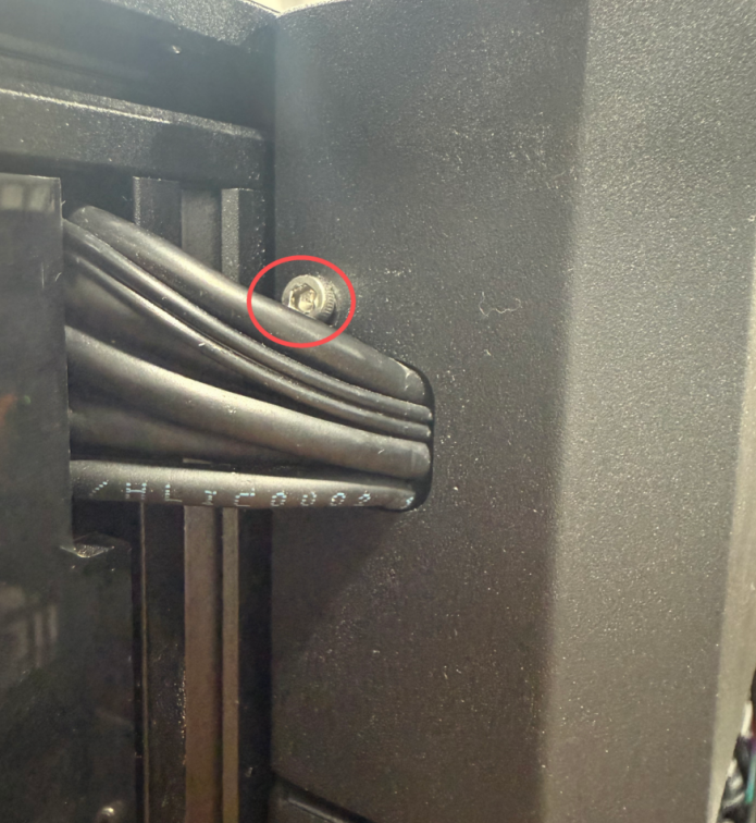
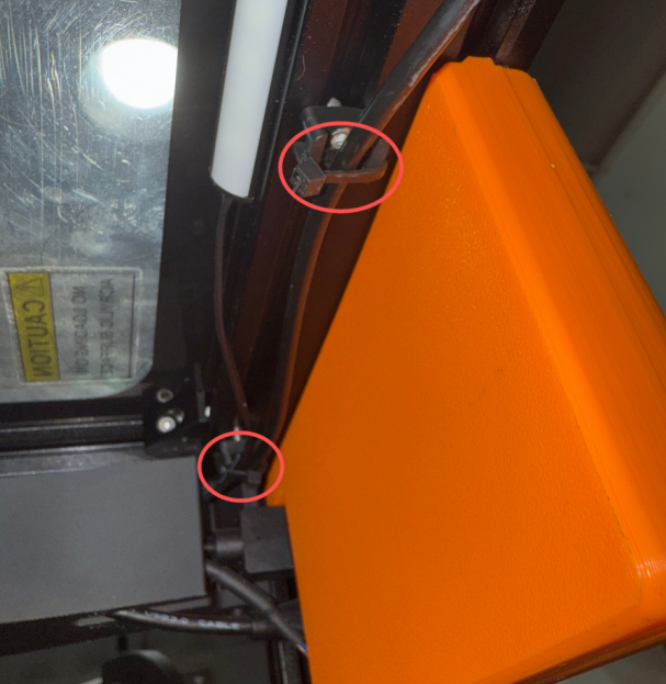
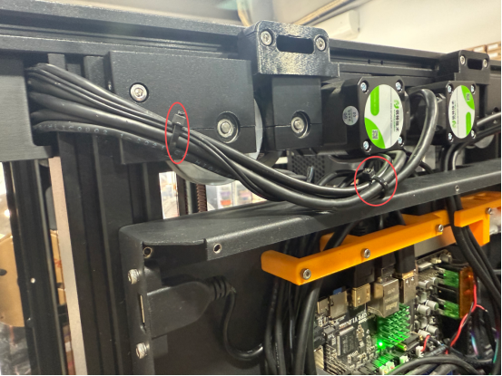
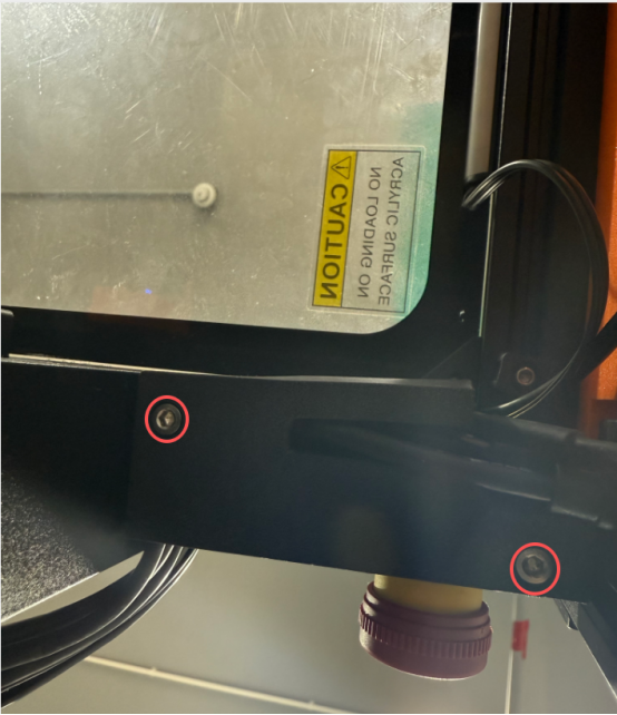
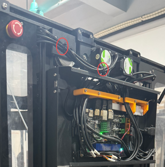
5.Cut the cable ties
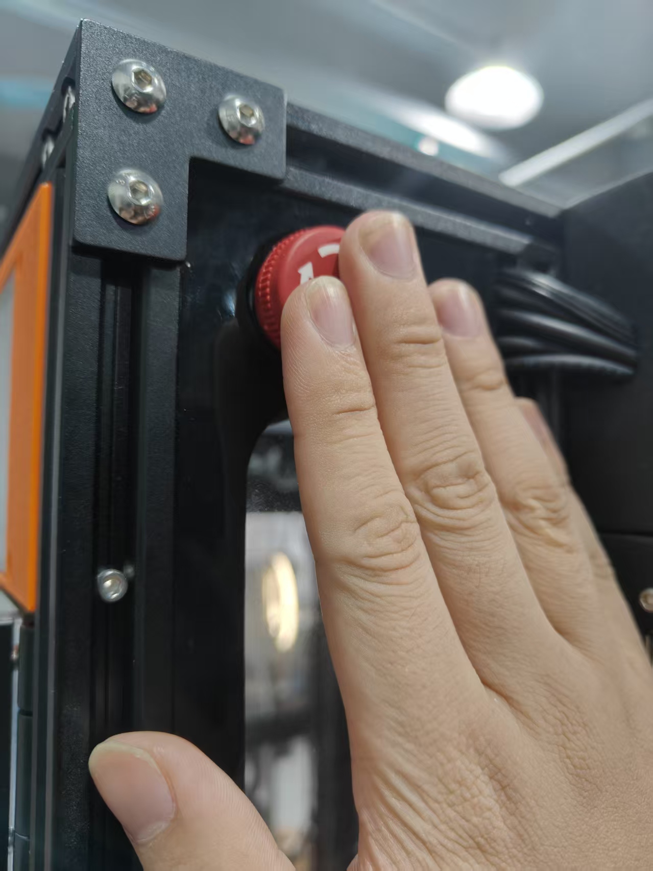
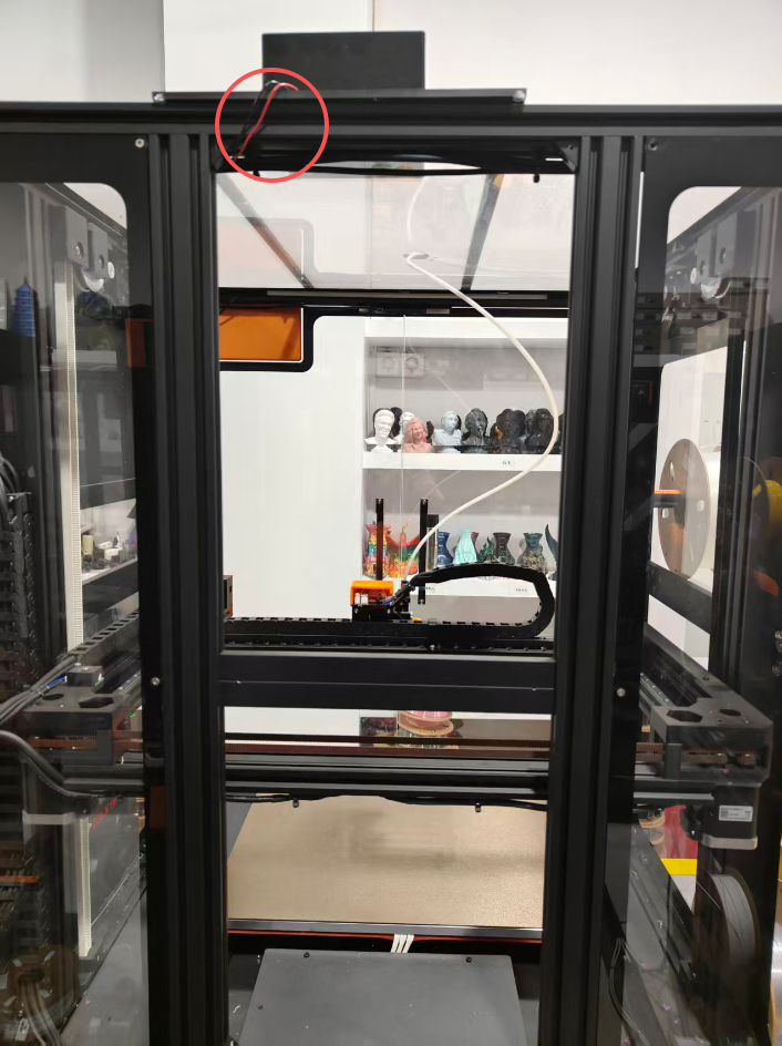
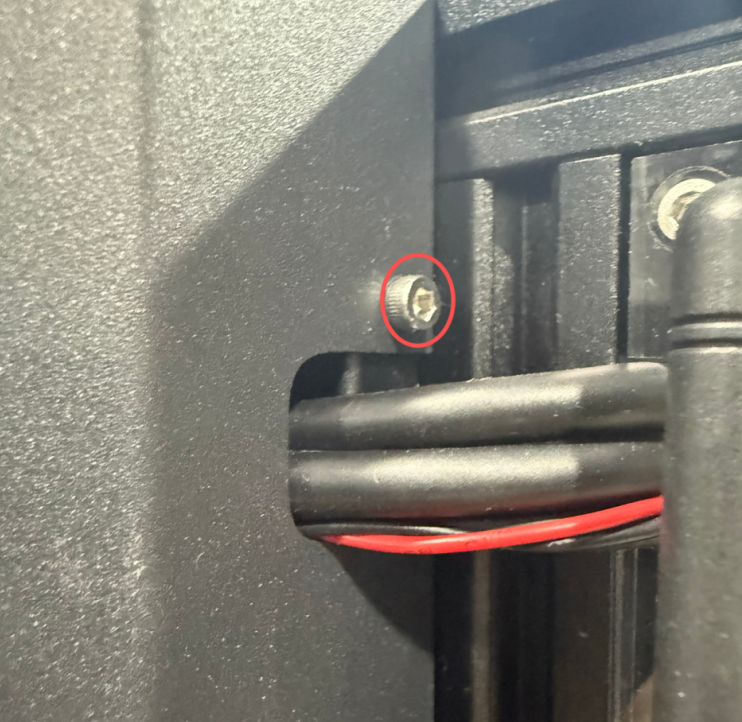
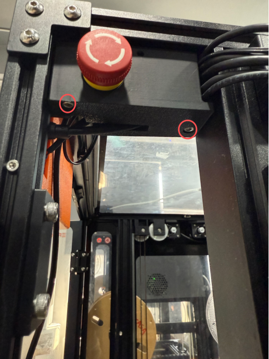
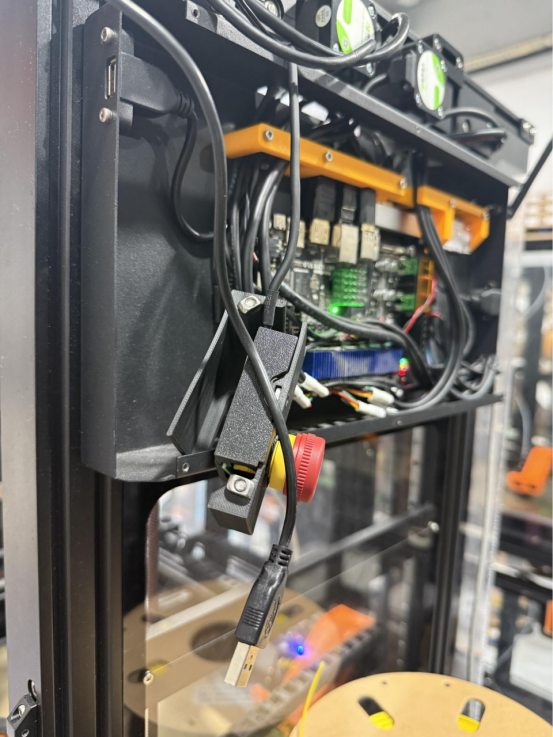
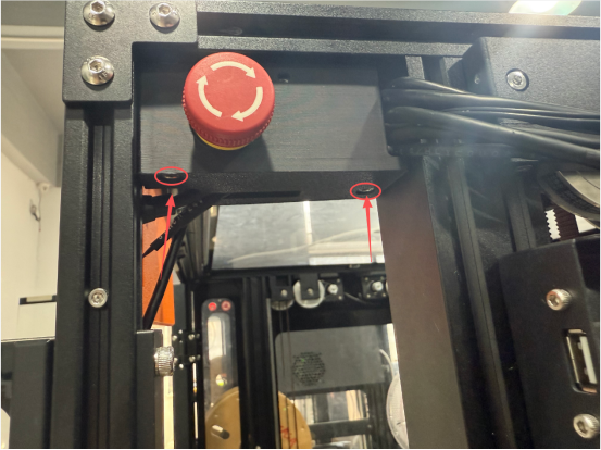
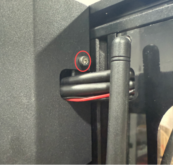
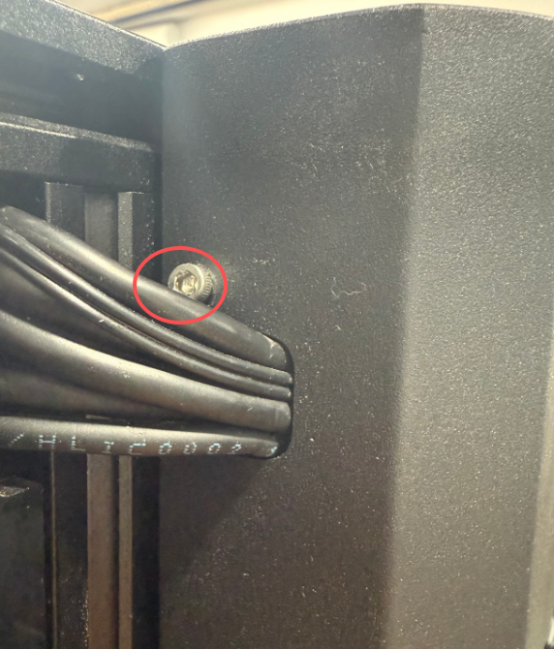
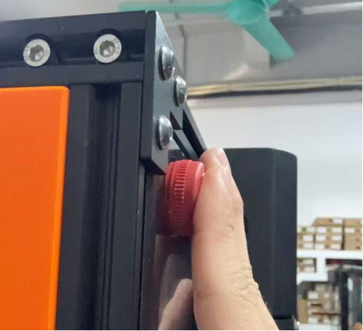
6.Unscrew the two screws at the bottom of the emergency switch box and remove the emergency switch box.
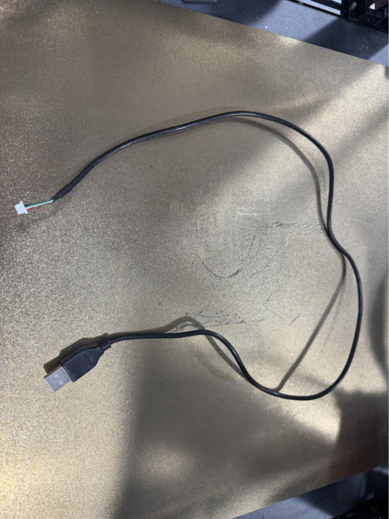
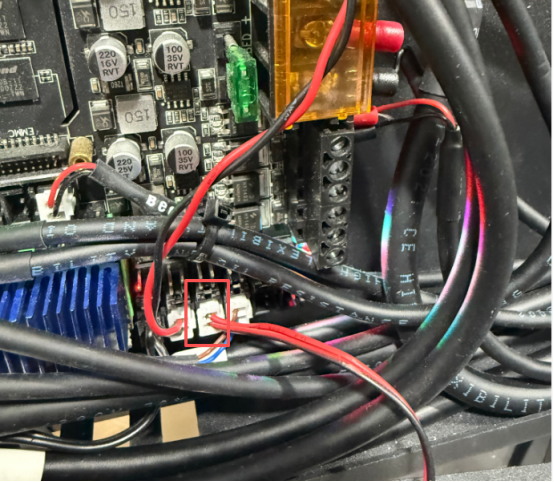
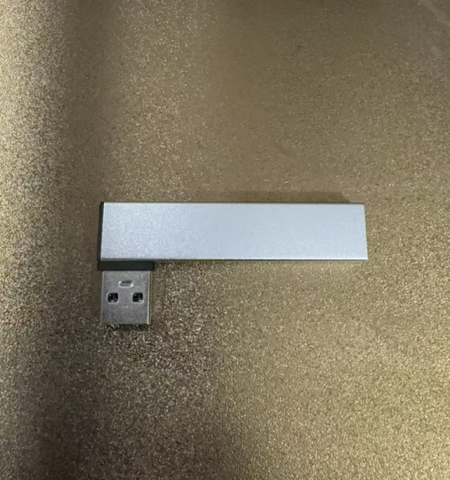
7.Remove the camera's USB cable.
8.Take out the new camera wiring
9.Insert the USB end into the docking station.
10.After inserting the wiring clip into the emergency switch box, tighten the two screws at the bottom.
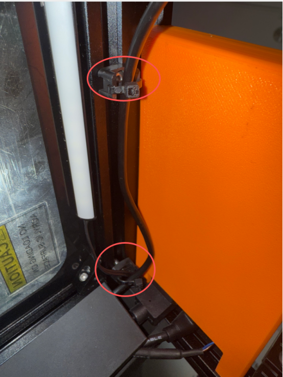
11.Secure the camera cable with cable ties
12.Then insert the external wires into the outer cover of the Z motor.

13.Finally, connect the motherboard fan and secure the motherboard cover.
¶ Replace dock
1.Turn off the printer
2.Remove the motherboard cover and motherboard fan cable terminals.
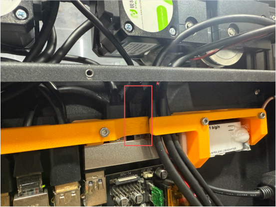
3.Remove the wire harness barrier.
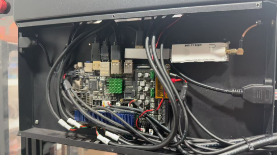
4.Remove the cables and WiFi module plugged into the docking station.
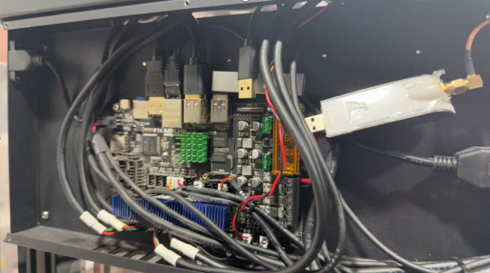
5.Remove docking station
6.Insert the new expansion dock into the motherboard.
7.Reconnect the cables and WiFi module to the docking station.
8.Reinstall the wire harness barrier.
9.Reconnect the fan cable and tighten the motherboard cover screws.